Notes for installation and commissioning
 | The accuracy of the TC temperature measurement is directly influenced by the cold junction measurement. Please note the following design guidelines!
|
Notes on measuring the cold junction temperature
The measurement and calculation of the correct temperature with TC elements requires the additional measurement of the so-called cold junction temperature (CJC). The cold junction temperature is measured by two RTDs. These are positioned very close to the thermocouple connection on the "backplane" (setting the TC material copper).
 Fig.10: TC/ RTD connections on the "backplane"
Examples:
- 1. An isothermal block → all TC connections on the "backplane" are located close together in one place and therefore have the same temperature:
- one RTD is sufficient; any other TC can be referenced to RTD1.
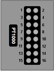 Fig.11: An isothermal block
- 2. Two isothermal blocks with different temperatures and each with its own RTD:
- the number of TCs on one and the other block can be freely selected, e.g. for EJ3318 TCs 1-3-4-7-8 close to RTD1 and TCs 2-5-6 close to RTD2.
- 3. If there is a temperature gradient across the connected connections of the TCs,
- an average temperature can be calculated by the PLC and provided in the process data. In this case, the TC channels should be referenced as follows
- for the 4-channel module, TC channels 1..2 on CJ1 and TC channels 3..4 on CJ2
- for the 8-channel module 1..4 on CJ1 and the TC channels 5..8 on CJ2
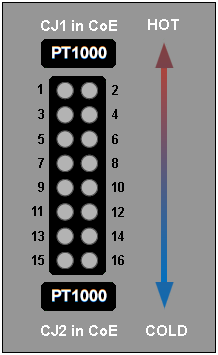 Fig.12: Temperature gradient across the connected connections of the TCs
- 4. If necessary, the TC channels can be routed to two different TC connectors. Follow the rules mentioned above!
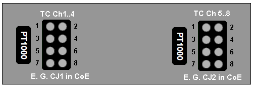 Fig.13: Routing of the TCs to two different TC connectors using the example of EJ3318
Setting the cold junction compensation
intern RTD Ch1 is set for each channel, the assignment can be selected separately for each channel in index 0x80n0:0C (n=0: channel 1 ... n=7: channel 8, depending on the number of channels).
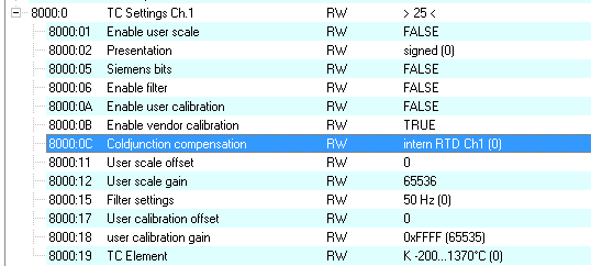 Fig.14: TC Settings using the example of channel 1, index 0x8000:0C
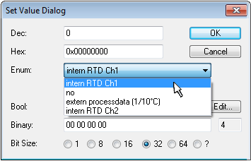 Fig.15: CJC selection dialog
Name | Value | Description |
|---|---|---|
intern RTD Ch1 | 0dec | Cold junction compensation is carried out via intern RTD Ch.1 of the module (default). |
no | 1dec | Cold junction compensation is not active. |
extern procecssdata (1/10°C) | 2dec | Cold junction compensation is carried out via the process data 0x160n (n = 0: channel 1 ... n = 7: channel 8, depending on the number of channels). These must then be mapped via the PDO assignment. |
intern RTD Ch2 | 3dec | Cold junction compensation is carried out via intern RTD Ch.2 of the module. |
Other settings:
- Filter: the index 0x8000:15 applies to all channels, pre-set 50 Hz
- Index 0x80n0:19 - Setting the TC element separately for each channel