LEDs
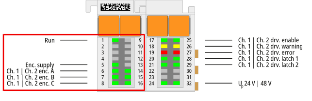
Display no. | Name | Comment | |
|---|---|---|---|
1 | Run | Status of the terminal in the EtherCAT network. | |
off | Status “Init” | ||
flashes | Status “Pre-Operational” | ||
single flash | Status “Safe-Operational” | ||
lit | Status “Operational” | ||
2 | -- | -- | |
3 | -- | -- | |
4 | -- | -- | |
5 | Enc. supply | Status of the encoder supply. Indicates that the encoder supply is present. | |
6 | Ch. 1 enc. A | Signal display encoder signal A, channel 1 | |
7 | Ch. 1 enc. B | Signal display encoder signal B, channel 1 | |
8 | Ch. 1 enc. C | Signal display encoder signal C, channel 1 | |
9 | -- | -- | |
10 | -- | -- | |
11 | -- | -- | |
12 | -- | -- | |
13 | -- | -- | |
14 | Ch. 2 enc. A | Signal display encoder signal A, channel 2 | |
15 | Ch. 2 enc. B | Signal display encoder signal B, channel 2 | |
16 | Ch. 2 enc. C | Signal display encoder signal C, channel 2 | |
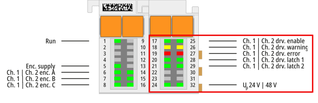
Display no. | Name | Comment |
|---|---|---|
17 | Ch. 1 drv. enable | Indicates that output stage channel 1 is enabled |
18 | Ch. 1 drv. warning | Indicates that the channel has issued a warning |
19 | Ch. 1 drv. error | Indicates that the channel is in error state |
20 | Ch. 1 drv. latch 1 | Signal display latch input A for channel 1 |
21 | Ch. 1 drv. latch 2 | Signal display latch input B for channel 1 |
22 | -- | -- |
23 | -- | -- |
24 | UP 24 V | Voltage indicator for the 24 V input voltage via the power contacts |
25 | Ch. 2 drv. enable | Indicates that output stage channel 2 is enabled |
26 | Ch. 2 drv. warning | Indicates that the channel has issued a warning |
27 | Ch. 2 drv. error | Indicates that the channel is in error state |
28 | Ch. 2 drv. latch 1 | Signal display latch input A for channel 2 |
29 | Ch. 2 drv. latch 2 | Signal display latch input B for channel 2 |
30 | -- | -- |
31 | -- | -- |
32 | 48 V | Voltage indicator for the motor supply |