Connection
Information on wiring can be found in the chapters Connection technology / wiring and Shielding concept.
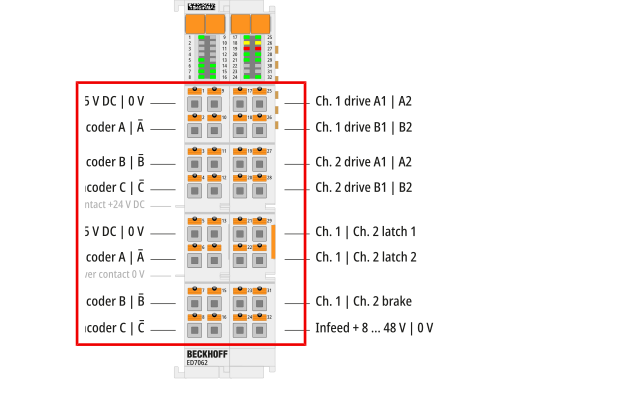
Terminal point | Name | Comment |
|---|---|---|
1 | Enc supply +5 V DC | 5 V output voltage to supply the encoder on channel 1 |
2 | Ch. 1 Enc A | Encoder signal input “A” for channel 1 |
3 | Ch. 1 Enc B | Encoder signal input “B” for channel 1 |
4 | Ch. 1 Enc C | Encoder signal input “C” for channel 1, configurable as zero pulse input (factory setting) or as latch input |
5 | Enc supply +5 V DC | 5 V output voltage to supply the encoder on channel 2 |
6 | Ch. 2 Enc A | Encoder signal input “A” for channel 2 |
7 | Ch. 2 Enc B | Encoder signal input “B” for channel 2 |
8 | Ch. 2 Enc C | Encoder signal input “C” for channel 2, configurable as zero pulse input (factory setting) or as latch input |
9 | Enc supply 0 V | Ground connection for the encoder supply at terminal point 1 |
10 | Ch. 1 Enc A̅ | Inverted input signal to “A” at terminal point 2 |
11 | Ch. 1 Enc B̅ | Inverted input signal to “B” at terminal point 3 |
12 | Ch. 1 Enc C̅ | Inverted input signal to “C” at terminal point 4 |
13 | Enc supply 0 V | Ground connection for the encoder supply at terminal point 5 |
14 | Ch. 2 Enc A̅ | Inverted input signal to “A” at terminal point 6 |
15 | Ch. 2 Enc B̅ | Inverted input signal to “B” at terminal point 7 |
16 | Ch. 2 Enc C̅ | Inverted input signal to “C” at terminal point 8 |
Notice | |
Control and load voltage supply The control and load voltage supplies must be both SELV or both PELV circuits. In the case of the PELV circuit, all-pole line protection is required for the control voltage. |
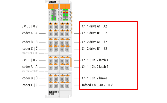
Terminal point | Name | Comment |
|---|---|---|
17 | Ch. 1 Drive A1 | Connections for the motor windings |
18 | Ch. 1 Drive B1 | |
19 | Ch. 2 Drive A1 | |
20 | Ch. 2 Drive B1 | |
21 | Ch. 1 latch 1 | Latch input A for channel 1 |
22 | Ch. 1 latch 2 | Latch input B for channel 1 |
23 | Ch. 1 brake | Digital output for controlling a brake on channel 1 |
24 | Infeed + 8…48 V | Input for the motor supply |
25 | Ch. 1 Drive A2 | Connections for the motor windings |
26 | Ch. 1 Drive B2 | |
27 | Ch. 2 Drive A2 | |
28 | Ch. 2 Drive B2 | |
29 | Ch. 2 latch 1 | Latch input A for channel 2 |
30 | Ch. 2 latch 2 | Latch input B for channel 2 |
31 | Ch. 2 brake | Digital output for controlling a brake on channel 2 |
32 | Infeed 0 V | Ground potential for all terminal points 17 to 32 |