PDO Assignment
The scope of the process data offered varies depending on the configured IO-Link ports.
“DeviceState Inputs Device” and “DeviceState Inputs” are selected by default. Device-specific PDOs (0x1A0n “Port (n-1) Process Data”) are only displayed after configuring on the respective port and restarting the EtherCAT system or reloading the configuration in Config mode; see Activating the configuration.
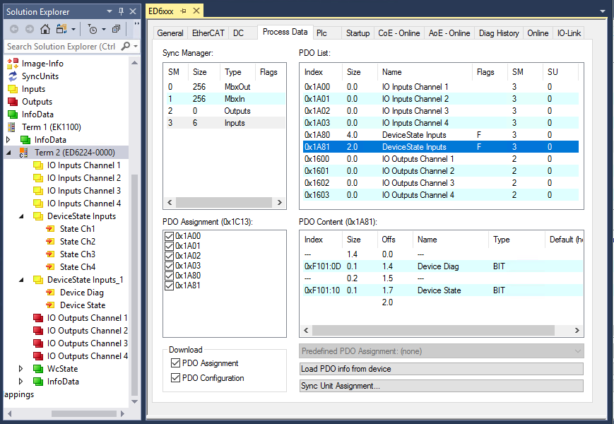 Fig.59: Illustration of the process data allocation, SM3 inputs using the ED6224 as an example
SM3, PDO Assignment 0x1C13 | |||
|---|---|---|---|
Index | Size (byte.bit) | Name | PDO content |
0x1A81 | 2.0 | DeviceState Inputs Device | Index 0xF101:0D - Device Diag |
0x1A80 | 4.0 | DeviceState Inputs | Index 0xF100:01 - State Ch1 |
0x1A00 | 0.0 - 32.0 | Port 1 Process Data | IO-Link device-specific / only active after configuration |
0x1A01 | 0.0 - 32.0 | Port 2 Process Data | IO-Link device-specific / only active after configuration |
0x1A02 | 0.0 - 32.0 | Port 3 Process Data | IO-Link device-specific / only active after configuration |
0x1A03 | 0.0 - 32.0 | Port 4 Process Data | IO-Link device-specific / only active after configuration |
 | Process data representation If data types are used that don’t conform to IEC61131-3, they are represented as octet strings. |
The status of the IO-Link ports 1 to 4 is displayed via index 0xF100:0n.
The indexes 0xF101:xx provide general diagnosis data.
Index | Size (byte.bit) | Name | Meaning |
|---|---|---|---|
0xF101:0D | 0.1 | Device Diag | Occurrence of events (on the device side) is reported via a status bit |
0xF101:10 | 0.1 | Device State | Interruption of communication with one of the slaves is reported via a status bit |
0xF100:01 | 1.0 | State Ch.1 | See table “Meaning of status byte Ch. 1 - Ch. 4” |
0xF100:02 | 1.0 | State Ch.2 | |
0xF100:03 | 1.0 | State Ch.3 | |
0xF100:04 | 1.0 | State Ch.4 |
The status bytes are divided into two nibbles.
Meaning Status byte Ch. 1 - Ch. 4 |
|---|
Low nibble: 0x_0 = Port disabled Combinations are possible and are displayed as addition of the values (s. note) |
Higher nibble: 0x1_ = Watchdog detected Combinations are possible and are displayed as addition of the values (s. note) |
| Addition of the values in case of simultaneously occurring diagnostic messages If messages occur simultaneously, the value is displayed as a sum in the Status byte of the relevant channel.
|