Connection and LEDs
| |
Risk of injury through electric shock and damage to the device! Bring the bus terminal system into a safe, de-energized state before beginning to mount, disassemble, or wire the bus terminals! |

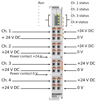 Fig.1: ED6224
Connection
Terminal point | Description | |
|---|---|---|
Abbreviation | No. | |
Ch 1 | 1 | Input 1 |
+24 V DC | 2 | +24 V |
Ch 2 | 3 | Input 2 |
+24 V DC | 4 | +24 V |
Ch 3 | 5 | Input 3 |
+24 V DC | 6 | +24 V |
Ch 4 | 7 | Input 4 |
+24 V DC | 8 | +24 V |
+24 V DC | 9 | +24 V |
0 V | 10 | 0 V |
+24 V DC | 11 | +24 V |
0 V | 12 | 0 V |
+24 V DC | 13 | +24 V |
0 V | 14 | 0 V |
+24 V DC | 15 | +24 V |
0 V | 16 | 0 V |
| |
Risk of device damage! The IO-Link devices must be powered from the 24 V power supply of the ED/EJ/EL6224 provided for this purpose, otherwise the IO-Link port may be damaged! |
LEDs
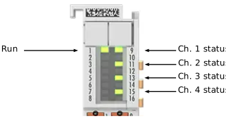 Fig.2: ED6224 – LEDs
Name | No. | Color | Meaning | |
|---|---|---|---|---|
RUN | 1 | green | This LED indicates the terminal’s operating state: | |
off | State of the EtherCAT State Machine: INIT = initialization of the terminal | |||
flashing | State of the EtherCAT State Machine: PREOP = function for mailbox communication and different default settings are applied | |||
single flash | State of the EtherCAT State Machine: SAFEOP = verification of the Sync Manager channels and the distributed clocks. | |||
on | State of the EtherCAT State Machine: OP = normal operating state; | |||
Ch. 1 - 4 status | 9, | green | on / off | State of the signal line (if configured as STD in / out) |
2 short flashes | Establishing IO-Link communication | |||
flashing continuously | IO-Link communication established and in operation | |||