Micro-increments
The "micro-increments" function offers the option to interpolate additional increments between the counted encoder increments and thus increase the resolution of the counter value.
Functional principle of micro-increments
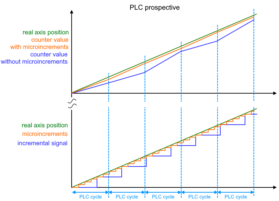
The following figure illustrates the functional principle of micro-increments. It is based on the interpolation of increments (orange) within real measured encoder increments (blue). To simplify the display, only four micro-increments are shown between the encoder increments. The current velocity is measured based on the internal period value measurement, and the micro-increments are interpolated accordingly. The interpolation resolution is 8 bits, which corresponds to 256 values. The counter value with micro-increments comes close to the real axis position. This is particularly useful at slow velocities, since an encoder with low resolution becomes a high-resolution axis encoder when micro-increments are enabled.
Example:
- Encoder with 1,024 lines
- 4-fold evaluation
- Micro-increments enabled, 8 bits
1024 lines * 4-fold evaluation * 256 micro-increments = 1,048,576 lines
 | DC mode for micro-increments In order to be able to use the micro-increments function in a meaningful way, the terminal should be operated in “DC-Synchron” or “DC-Synchron (input based)” mode. Due to the distributed clocks technology the counter value is determined in a cyclically constant manner. |
Microincrements sequence
- Enable microincrements via the index 0x80n0:0A “Enable micro increments”
- The microincrements are represented in the last 8 bits of the counter value in the input process data “Counter value” (0x60n0:11).
- The period value of the input signal should be greater than 1.34 µs, so that the microincrements can still be calculated. If this is not the case, the violation is displayed in the input process data “Extrapolation stall” (0x60n0:08).
- If the “Extrapolation stall” bit is TRUE, the 8 bits of the microincrements in the “Counter value” are set to zero.