Connection
| |
Risk of electric shock and damage of device! Bring the bus terminal system into a safe, powered down state before starting installation, disassembly or wiring of the bus terminals! |

 Fig.1: ED4072
Notice | |
Cable lengths > 30 m For cable lengths > 30 m, suitable overvoltage protection (Surge-Protection) must be provided (e g. EL9540-0010) if corresponding interference could affect the signal cable. |
Terminal point | Description | Internally connected with connection | Max. current carrying capacity *) | |
|---|---|---|---|---|
Abbreviation | No. | |||
Ch1 analog output | 1 | Voltage/current output, channel 1 | - | overload protected |
Ch2 analog output | 2 | Voltage/current output, channel 2 | - | overload protected |
n.c. | 3 | - | - | - |
n.c. | 4 | - | - | - |
+24 V DC | 5 | +24 V | 6; 7, +24 V power contact | 1 A |
+24 V DC | 6 | +24 V | 5, 7, +24 V power contact | 1 A |
+24 V DC | 7 | +24 V | 5, 6, +24 V power contact | 1 A |
Shield | 8 | Shield connection | 16 | 1 A ***) |
GND | 9 | Analog ground (reference potential for Ch1 … Ch2) | 10 | 100 mA **) |
GND | 10 | Analog ground (reference potential for Ch1 … Ch2) | 9 | 100 mA **) |
n.c. | 11 | - | - | - |
n.c. | 12 | - | - | - |
0 V | 13 | 0 V | 14, 15, 0 V power contact | 1 A |
0 V | 14 | 0 V | 13, 15, 0 V power contact | 1 A |
0 V | 15 | 0 V | 13, 14, 0 V power contact | 1 A |
Shield | 16 | Shield connection | 8 | 1 A ***) |
*) Constant current; short-term higher currents are to be avoided and can lead to thermal overload (damage). | ||||
Voltage output 0 … 10 V / -10 … +10 V
 Fig.2: Connection example ED4072, voltage output, 2-/4-wire
- 2-wire: 2-pin voltage output;
- 4-wire: with additional 24 V supply for the actuator
Current output -20 / 0 / +4 … +20 mA
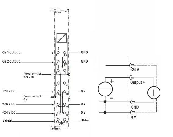 Fig.3: Connection example ED4072, current output, 2-/4-wire
- 2-wire: 2-pin current output;
- 4-wire: with additional 24 V supply for the actuator