Device diagnostic functions
Diagnostics in the CoE
The following device information can be read from the CoE:
Index | Name | Meaning |
|---|---|---|
0xF900:11 | Operating Time | operating time of the device in [min], cannot be deleted |
0xF900:12 | Device Temperature | current internal terminal temperature in [°C]. |
0xF900:13 | Min. Device Temperature | minimum value ever observed by the terminal in [°C], cannot be deleted |
0xF900:14 | Max. Device Temperature | maximum value ever observed by the terminal in [°C], cannot be deleted |
0xF900:15 | Supply Voltage | Informative display of the power contact voltage, measurement uncertainty ±1.2 V in the range 20..29 V. Measurement is not guaranteed for voltages outside this range! |
LED Status
The status of the terminal LEDs can be read electronically as follows:
Index | Name | Meaning |
|---|---|---|
0xF915:01 | RUN | EtherCAT Status |
0xF915:02 | Ch1 steady | Steady state Channel 1 |
0xF915:03 | Ch1 warning | Channel 1 warning |
0xF915:04 | Ch1 error | Channel 1 error |
0xF915:07 | DI1 | Digital input 1 |
0xF915:08 | DO1 | Digital output 1 |
0xF915:09 | Up 24 V | Supply voltage |
0xF915:0A | Ch2 steady | Steady state channel 2 |
0xF915:0B | Ch2 warning | Channel 2 warning |
0xF915:0C | Ch2 error | Channel 2 error |
0xF915:0E | DI2 | Digital input 2 |
0xF915:0D | DO2 | Digital output 2 |
The status of the optical displays (LEDs) in the device can be read out electronically in CoE 0xF915 LED Status, e.g. for simultaneous LED display in the visualization.
These are four bytes that describe the RGB value and the light status:
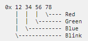
- Byte 1 (from left to right): Flashing/lighting code
- 0x00: Off/ not available
- 0x01…0x14: 1..20 Hz
- 0x80: EtherCAT PreOp
- 0x81: EtherCAT SafeOp
- 0x82: EtherCAT Boot
- 0xFF: On/ available
- Byte 2..4:
- 0x00: Off
- 0xFF: On
Examples:
- 0x 00 00 00 00: LED not present
- 0x FF 00 00 00 : LED is on, RGB =0, i.e. not illuminated, meaning: LED is present
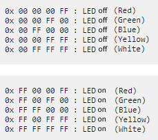 Fig.77: Examples LED status