Basic function principles
- The products are intended for the connection of force sensors that work with strain gauge measuring bridges. This allows weights, torques or vibrations to be recorded.
- This product is not a stand-alone scale, but is intended for use only in conjunction with a PLC/Controller.
- A full bridge must be connected. If only a quarter or half bridge is available, external auxiliary bridges must be added. The nominal value must then be adjusted accordingly.
- If the UExc supply provided by the product is used, the product must be used in 6-wire operation or bridges must be set between UExc and USense. The supply voltage is not passed on internally to theUSense channels.
- Several strain gauges can also be connected in parallel. When using the UExc supply provided, the maximum supply current specified in the technical data must be observed.
- The change of the quotient of the bridge voltage to the reference voltage corresponds to the relative force acting on the load cell. The quotient is output separately as process data as the value of the ratio of the two voltages in mV/V or converted into a weight.
- The two analog channels for the measurement of bridge and reference voltage are not calibrated by the manufacturer, since this is not required for the relative measurement in strain gauge mode. This means that different values can be measured for the same signal source with different sources. If the products output identical process values for identical applied voltages, meaning that they are exchangeable, each channel must be calibrated by the user by making settings for each channel in the CoE. User calibration or user scaling can be used for this purpose.
- The product has wire break detection for USense. There is no wire break detection for UBridge. If one of the bridge lines is broken, however, the voltage measured there generally moves towards the end value, thus displaying an error in the status PDO. A wire break at UExc can be detected via the thresholds of Range Error (0x801D:27/28, 0x805D:27/28) and Range Warning (0x801D:2D/3D, 0x805D: 2D/3D) and in the corresponding USense channel. The default settings lead to an error if the measured supply is <1 V.
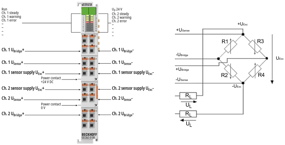 Fig.19: ED3362-0100, 6-wire connection
Overview of commands
The product has several command areas
- 0xFB00 DEV Command
applies to the entire product - 0xB030 RMB Command Ch.1
applies to measuring bridge channel 1 (RMB Ch.1) - 0xB070 RMB Command Ch.2 [only for ED3362, ED3362-0100]
applies to measuring bridge channel 2 (RMB Ch.2)
The following commands are supported by the product
Command | Name | Meaning | Command area |
|---|---|---|---|
0x3001 | CMD_AIRESET_ALL | All counters and drag indicators are reset | 0xFB00 |
0x301n | CMD_AIRESET_ | The drag indicator (PeakHold) is reset | 0xFB00 |
0x302n | CMD_AIRESET_ | The range error counter is reset | 0xFB00 |
0x303n | CMD_AIRESET_ | The limit counter is reset | 0xFB00 |
0x304n | CMD_AIRESET_ | The range warning counter is reset | 0xFB00 |
0x313n | CMD_SET_TARE(x) | A tare value is determined. The values are temporarily saved with this command | 0xFB00 |
0x314n | CMD_RESET_TARE(x) | The current tare value is deleted | 0xFB00 |
0x318n | CMD_STORE_TARE(x) | The current tare value is stored in the EEPROM (secured against power failure) | 0xFB00 |
0x3190 | CMD_SET_USEROFFSET_TMP Ch. 1 / Ch. 2 | A current value is determined in the user scale offset (0x80nD:0C) and the user scale (0x80n0:01) is activated. The values are temporarily saved with this command | 0xFB00 |
0x31A0 | CMD_RESET_USEROFFSET | The current value in the User Scale Offset (0x80nD:0C) is deleted and User Scale (0x80n0:01) is deactivated | 0xFB00 |
0x31B0 | CMD_STROE_USEROFFSET | User Scale Offset (0x80nD:0C) with activated User Scale (0x80n0:01) are stored fixed in the EEPROM | 0xFB00 |
0x0101 | CMD_OFFSET_ADJ | The offset calibration for the sensor calibration is performed [Zero balance] | 0xB030, 0xB070 |
0x0102 | CMD_GAIN_ADJ | The gain adjustment for the sensor calibration is performed [Sensitivity] | 0xB030, 0xB070 |
The mapping of channel x to command index n is as follows:
Channel x | Command index n |
|---|---|
UBridge Ch.1 | 0 |
USense Ch.1 | 1 |
RMB Ch.1 | 2 |
UBridge Ch.2 | 4 |
USense Ch.2 | 5 |
RMB Ch.2 | 6 |