Watchdog behavior when the PLC is inactive
The PWM outputs can also adopt the behavior defined in index 0x80n0:05, “Watchdog”, when the PLC is inactive or when there is no communication with the PLC or communication with the PLC is faulty. This is also the case, for example, when the PLC is restarted if the device is already in the OP state but the PLC is not yet providing valid data. Proceed as follows:
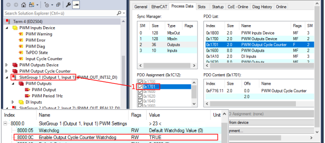 Fig.29: PWM watchdog settings when the PLC is inactive
- 1. To enable the optional PDO 0x1701 “PWM Output Cycle Counter”, select SM2 on the “Process Data” tab and enable the PDO in the “PDO Assignment (0x1C12)” field.
- The additional PDO “PWM Output Cycle Counter” appears in the output data. It is a 16 bit counter and is available once for the entire device.
- 2. Cyclic incrementation of the “PWM Output Cycle Counter” process data value
If this PDO is enabled, the variable must be incremented cyclically by +1 from the control. The variable overflow is handled by the device. - 3. Channel-by-channel activation of “Output Cycle Counter” monitoring via the CoE directory index 0x80n0:0C “Enable Output Cycle Counter Watchdog” = TRUE
- The device is now monitoring the “PWM Output Cycle Counter” counter.
- If the object: 0x80n0:0C “Enable Ouput Cycle Counter Watchdog” is set to TRUE without first activating the PDO “PWM Output Cycle Counter”, this is displayed as a warning in the DiagMessages: DiagMessage,
Text ID: “0x4110 Output Cycle Counter watchdog activated without a mapped PDO” - 4. The watchdog event is triggered if there is no change in the counter within the PD watchdog time (default 100 ms).
- For all channels with active output cycle counter monitoring (0x80n0:0C = TRUE), the behavior defined for the respective channel at index 0x80n0:05 “Watchdog” (see the chapter “Watchdog behavior in case of a bus error”).
Notice | |
Notes on watchdog behavior when the PLC is inactive
|
Diagnostics for an inactive PLC
The triggering of a watchdog event – for example, due to an inactive PLC – is indicated by:
LED 2: “Dev error” | Process data | DiagMessages |
|---|---|---|
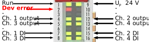
“Dev error” lights up red
| The number of events that have occurred can be read from the error counter: 0xFA16:16 “Output Cycle Counter Error”.
| Text ID: 0x8114 Output Cycle Counter watchdog has triggered
|