“Digital input” | ModuleIdent 0x2009C8
The binary signal is output via the “Input” process data value.
The digital input module provides the following functions:
- Parameterizable input characteristics (0x80n0:11 “Input Type”)
- Parameterizable filter time (0x80n0:12 “Filter Time”)
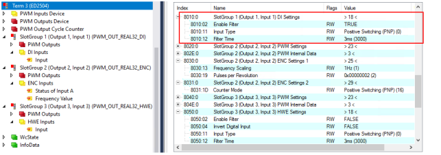 Fig.30: Digital input settings
Parameterizable input characteristics
The digital input can be interpreted as having either a positive switching or ground switching characteristic. This is defined at 0x80n0:11 “Input Type” (n = 1 for DI 1, n = 3 for DI 2, n = 5 for DI 3, n = 7 for DI 4):
Standard digital | Positive switching | |
|---|---|
0x80n0:11 „Input Type“ | Positive Switching (PNP) |
Signal voltage “0” | -3…+1.5 V DC |
Signal voltage “1” | 2.7…28 V DC |
Standard digital | Ground switching | |
|---|---|
0x80n0:11 „Input Type“ | Ground Switching (NPN) |
Signal voltage “0” | 2.5…28 V DC |
Signal voltage “1” | -3…+1 V DC |
In this operation mode, an additional pull-up resistor is connected to V+. | |
 | Sensors with open collector output circuits A sensor with an open collector output circuit corresponds to the “Input Type”: “Ground Switching (NPN)”.
|
Parameterizable filter time
The digital input module provides a parameterizable filter time. This can be used to suppress interference, such as bouncing of a switch signal. Signals with a pulse duration shorter than the set filter time are suppressed.
Filter function sequence
- The filter is enabled on delivery, index 0x80n0:02 “Enable Filter” = TRUE
- The filter is parameterized via index 0x8n0:12 “Filter Time”. The minimum pulse duration depends on the set software filter (see following table).
Available filter times:
Index 0x80n0:12 “Filter Time” | Meaning |
|---|---|
500dec: 500 µs | Signals < 500 µs are suppressed |
750dec: 750 µs | Signals < 750 µs are suppressed |
1,000dec: 1 ms | Signals < 1 ms are suppressed |
3,000dec: 3 ms | Signals < 3 ms are suppressed (default) |
10,000dec: 10 ms | Signals < 10 ms are suppressed |
20,000dec: 20 ms | Signals < 20 ms are suppressed |
- The filter is disabled by setting index 0x80n0:02 “Enable Filter” = FALSE. In this case, the input signal is only filtered via the hardware. In this case, the filter value is typically 10 µs.