Applying new duty cycle and/or frequency values
Two options are available for applying new duty cycle and/or frequency values:
- 1. Applying new values in the default setting (see Example 1)
In the default setting, new process data specifications for “PWM Duty Cycle” and “PWM Frequency” are applied only after the currently running period has elapsed and one additional full period has passed.
This prevents distortion of the output signal, ensuring that no glitches occur. - 2. Applying new values with low latency in 1-channel mode (see Example 2)
In 1-channel mode, the cyclic update of new values (“PWM Duty Cycle”, “PWM Frequency”) is supported with low latency. In this case, the value is applied after the currently running period has elapsed; no additional full period is waited for.
To do this, the following parameterizations are required: - Select the desired configuration for SlotGroup 1.
- Select an “Empty” module in SlotGroup 2, SlotGroup 3, and SlotGroup 4. As a result, channels 2, 3, and 4 are no longer functional.
- In the CoE directory, set:
0xF817:01 “Enable Low Latency Output Slot 1” = TRUE.
Example 1: 0xF817:01 “Enable Low Latency Output Slot 1” = FALSE (default)
New process data values (“PWM Duty Cycle”, “PWM Frequency”) are applied once the current period has ended and another period has elapsed.
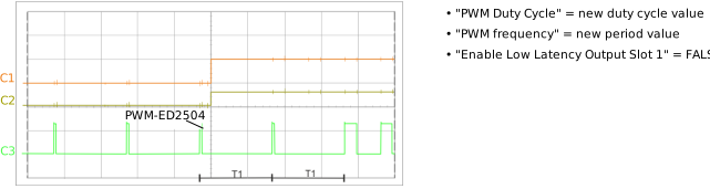 Fig.21: Diagram “Enable Low Latency Output Slot1” = FALSE (default)
Example 2: “Enable Low Latency Output Slot 1” = TRUE, application with low latency
New process data values (“PWM Duty Cycle”, “PWM Frequency”) are applied immediately after the current period ends.
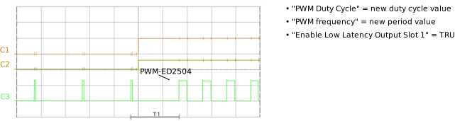 Fig.22: Diagram “Enable Low Latency Output Slot1” = TRUE
Legend for the figures in the examples shown above: C1: Specification of the frequency using the “PWM Frequency” process data value |