Externally supplied power for the output signal
The output voltage level of the PWM outputs depends on the externally supplied voltage at the connection points.
- 1. The voltage must be supplied via the following terminals:
- Terminal 7, 15: Externally supplied 5…24 V DC supply
- Terminal 8, 16: Ground reference for externally supplied power
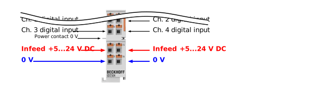 Fig.4: ED2504 – external power supply
- 2. Before applying voltage, ensure that all four actuators connected to the PWM outputs are compatible with this voltage range.
The following tolerances apply:
Externally supplied voltage | Tolerance |
|---|---|
Min. 5 V DC | – |
Max. 24 V DC | up to +20% (up to 28.8 V) |
Notice | |
Notes on the externally supplied voltage
|
Notice | |
Shared ground reference for external power supply If the actuators are controlled via the PWM outputs but are not powered by the externally supplied voltage, a common ground connection between the EtherCAT Terminal and the external power supply must be ensured. |
Diagnostics of missing or insufficient externally supplied voltage
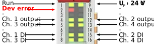
If there is no external supply voltage or if the voltage is too low, this is indicated by:
LED 2: “Dev error”, | Process data | DiagMessages: |
|---|---|---|
“Dev error” lights up red
| Warning bit = TRUE | For voltages < 4.75 V: |
Error bit = TRUE | for voltages < 4.5 V: |