LEDs
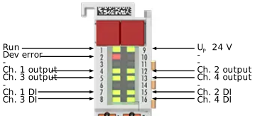 Fig.3: ED2504 – LEDs
Name | No. | Color | Meaning | |
|---|---|---|---|---|
Run | 1 | green | This LED indicates the terminal's operating state: | |
off | State of the EtherCAT State Machine: INIT = initialization of the terminal | |||
flashing | State of the EtherCAT State Machine: PREOP = function for mailbox communication and different default settings set | |||
Single flash | State of the EtherCAT State Machine: SAFEOP = verification of the Sync Manager channels and the distributed clocks. | |||
on | State of the EtherCAT State Machine: OP = normal operating state; | |||
flickering | State of the EtherCAT State Machine: BOOTSTRAP = Function for | |||
Dev error | 2 | red | on | Error indicator: An error has occurred, e.g., due to incorrect configuration or undervoltage. For details, see the “Diagnostics” chapter |
Ch. 1 output | 4 | green | on | PWM output signal is present on channel 1 |
off | No output signal | |||
Ch. 3 output | 5 | green | on | PWM output signal is present on channel 3 |
off | No output signal | |||
Ch. 1 DI | 7 | green | on | An input signal is present at the digital input of channel 1 |
off | No input signal at the digital input | |||
Ch. 3 DI | 8 | green | on | An input signal is present at the digital input of channel 3 |
off | No input signal at the digital input | |||
UP 24 V | 9 | green | on | 24 V peripheral voltage (power contacts) is present. |
off | Peripheral voltage (power contacts) is not present or is below 12 V. | |||
Ch. 2 output | 12 | green | on | PWM output signal is present on channel 2 |
off | No output signal | |||
Ch. 4 output | 13 | green | on | PWM output signal is present on channel 4 |
off | No output signal | |||
Ch. 2 DI | 15 | green | on | An input signal is present at the digital input of channel 2 |
off | No input signal at the digital input | |||
Ch. 4 DI | 16 | green | on | An input signal is present at the digital input of channel 4 |
off | No input signal at the digital input | |||