Connection
| |
Risk of injury through electric shock and damage to the device! Bring the bus terminal system into a safe, de-energized state before beginning to mount, disassemble, or wire the bus terminals! |

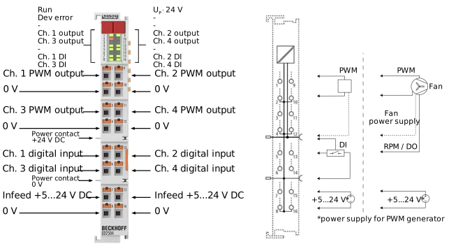 Fig.2: ED2504
Terminal point | Description | |
|---|---|---|
Abbreviation | No. | |
Ch 1 output | 1 | PWM output 1 |
0 V | 2 | 0 V (internally connected to terminal points 4, 8, 10, 12, 16, and the negative power contact) |
Ch 3 output | 3 | PWM output 3 |
0 V | 4 | 0 V (internally connected to terminal points 2, 8, 10, 12, 16, and the negative power contact) |
Ch 1 DI | 5 | Digital input 1 |
Ch 3 DI | 6 | Digital input 3 |
Infeed 5…24 V | 7 | Externally supplied 5…24 V DC power |
0 V | 8 | Ground reference for externally supplied power |
Ch 2 output | 9 | PWM output 2 |
0 V | 10 | 0 V (internally connected to terminal points 2, 4, 8, 12, 16, and the negative power contact) |
Ch 4 output | 11 | PWM output 4 |
0 V | 12 | 0 V (internally connected to terminal points 2, 4, 8, 10, 16, and the negative power contact) |
Ch 2 DI | 13 | Digital input 2 |
Ch 4 DI | 14 | Digital input 4 |
Infeed 5…24 V | 15 | Externally supplied 5…24 V DC power |
0 V | 16 | Ground reference for externally supplied power |
Notice | ||
 | Please note the additional information and instructions Please follow the instructions below and refer to the information in the technical specifications! | |
 | Note on connecting two-wire cables If you are using two-wire cables, we recommend using a shielded cable for the PWM signal. |
Notes on connecting and operating the digital inputs
| Sensors with open collector output circuits A sensor with an open collector output circuit corresponds to the “Input Type”: “Ground Switching (NPN)”.
|
| Digital input wiring
|
| Maximum cable length to the sensor/encoder
|
Notice | |
Fast digital inputs – interference from interfering devices Please note that the input wiring has very little filtering. It has been optimized for fast signal transmission from the input to the evaluation unit. In other words, rapid level changes/pulses in the µs range and/or high-frequency interference signals from devices (e.g. proportional valves, stepper motor or DC motor output stages) arrive at the evaluation unit almost unfiltered/unattenuated. These interferences can be incorrectly detected as a signal.
|