Interference-free bus terminals
 | Implementing interference-free bus or EtherCAT Terminals in safety applications When a bus terminal or EtherCAT Terminal is described as interference-free, this means that the downstream terminal will be passive in a safety application (e.g., during all-pole disconnection of a potential group). |
Notice | |
Note the hardware version Please refer to the “Technical data” and “Firmware compatibility” sections for information on the hardware version and interference-free nature of the respective bus terminal! |
The terminals regarded as interference-free at the point that this document was drafted are listed in the following tables along with their respective hardware versions.
Bus terminals
Terminal name | From hardware version |
|---|---|
KL2408 | 05 |
KL2809 | 02 |
KL2134 | 09 |
KL2424 | 05 |
KL9110 | 07 |
ED Terminals
Terminal name | From hardware version |
|---|---|
ED2008 | 00 |
ED2032 | 00 |
ED2034 | 00 |
ED2807 | 00 |
ED2809 | 00 |
ED2828 | 00 |
ED2838 | 00 |
ED2887 | 00 |
ED2889 | 00 |
ED9100 | 00 |
ED9110 | 00 |
ED9184 | 00 |
ED9410 | 00 |
EL Terminals
Terminal name | From hardware version |
|---|---|
EL2004 | 15 |
EL2008 | 07 |
EL2014 | 00 |
EL2022 | 09 |
EL2024 | 06 |
EL2034 | 06 |
EL2042 | 06 |
EL2044 | 01 |
EL2068 | 00 |
EL2212 | 00 |
EL2258 | 00 |
EL2407 | 00 |
EL2409 | 00 |
EL2489 | 00 |
EL2809 | 01 |
EL2819 | 00 |
EL2828 | 00 |
EL2838 | 00 |
EL2869 | 00 |
EL2872 | 01 |
EL2878-0005 | 00 |
EL9110 | 13 |
EL9184 | 00 |
EL9185 | 00 |
EL9186 | 00 |
EL9187 | 00 |
EL9410 | 16 |
ELX Terminals
Terminal name | From hardware version |
|---|---|
ELX1052 | 00 |
ELX1054 | 00 |
ELX1058 | 00 |
ELX2002 | 00 |
ELX2008 | 00 |
ELX2792 | 00 |
ELX3152 | 00 |
ELX3158 | 00 |
ELX3181 | 00 |
ELX3184 | 00 |
ELX3202 | 00 |
ELX3204 | 00 |
ELX3252 | 00 |
ELX3312 | 00 |
ELX3314 | 00 |
ELX3351 | 00 |
ELX4154 | 01 |
ELX4181 | 00 |
ELX5151 | 00 |
ELX6233 | 00 |
ELX9560 | 03 |
External wiring
The following requirements are to be ensured by the system manufacturer and must be incorporated into the user documentation.
- IP54 protection class
The terminals must be installed in IP54 control cabinets to assure the required IP54 protection class. - Power supply
The standard terminals must be supplied with 24 V by an SELV/PELV power supply unit with an output voltage limit of Umax = 60 V in the event of a fault. - Prevention of feedback
Feedback can be prevented through different measures. These are described below. In addition to mandatory requirements, there are also optional requirements – only one of these must be selected. - Do not switch loads with a separate power supply
Loads that have their own power supply may not be switched by standard terminals, since in this case feedback via the load cannot be ruled out. - A negative example here could be activating an STO input for a variable frequency drive.
Exceptions to the general requirement are only permitted if the manufacturer of the connected load guarantees that feedback to the control input cannot occur. This can be achieved, for example, through compliance with load-specific standards. - Option 1: Ground return and all-pole disconnection
The ground connection for the connected load must be fed back to the safely switched ground. - If either
a) the load’s ground is not connected back to the terminal, or
b) the ground is not safely switched but permanently connected
, it is necessary to rule out faults related to short circuits with external potential in order to achieve Cat. 4 PLe in accordance with DIN EN ISO 13849-1:2007 or SIL 3 in accordance with IEC 61508:2010 (see the overview in the chapter “Effect of the options on the safety level”). - Option 2: Excluding cable short-circuiting faults
If option 1 is not feasible, the ground return and all-pole disconnection can be dispensed with if the danger of feedback due to a cable short-circuit can be excluded by other measures. These measures, which can be implemented as alternatives, are described in the following sections. - a) Option 1: Load connection using separate sheathed cables
The non-safely switched potential for the standard terminal may not be grouped inside the same sheathed cable as other potential-conducting lines. (Fault exclusion, see DIN EN ISO 13849-2:2013, Table D.4) - b) Option 2: Wiring is kept internal within the control cabinet
All loads connected to the non-safe standard terminals must be located in the same control cabinet as the terminals. The cables are routed entirely inside the control cabinet. (Fault exclusion, see DIN EN ISO 13849-2:2013, Table D.4) - c) Option 3: Dedicated earth connection per conductor
All conductors connected to the non-safe standard terminals are protected by their own earth connection. (Fault exclusion, see DIN EN ISO 13849-2:2013, Table D.4) - d) Option 4: Wiring permanently (fixed) installed and protected against external damage
All conductors connected to the non-safe standard terminals are permanently fixed in place and protected against external damage, for example, by a cable channel or conduit. - The options' effect on the safety level
In principle, standard terminals in safely switched potential groups are not an active part of the safety controller. This means that the safety level attained is solely defined by the higher-level safety controller: the standard terminals are not included in the calculation! However, the wiring of the standard terminals can lead to limitations on the maximum safety level that can be achieved.
There are different maximum achievable safety levels which are dependent on the selected solution option (see Option 1 and Option 2) for preventing feedback and the applicable safety standard, and these are summarized in the following table:
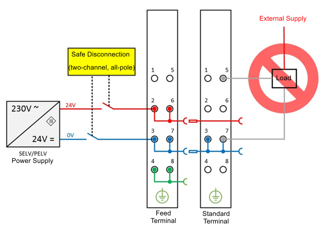 Fig.1: Negative example – active load
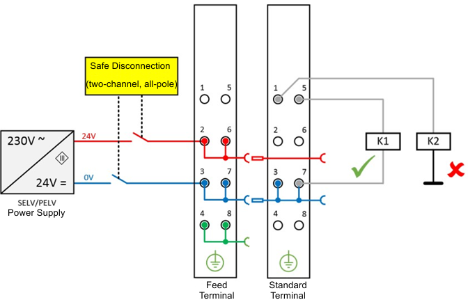 Fig.2: Ground connection of the load: correct (K1) and incorrect (K2)
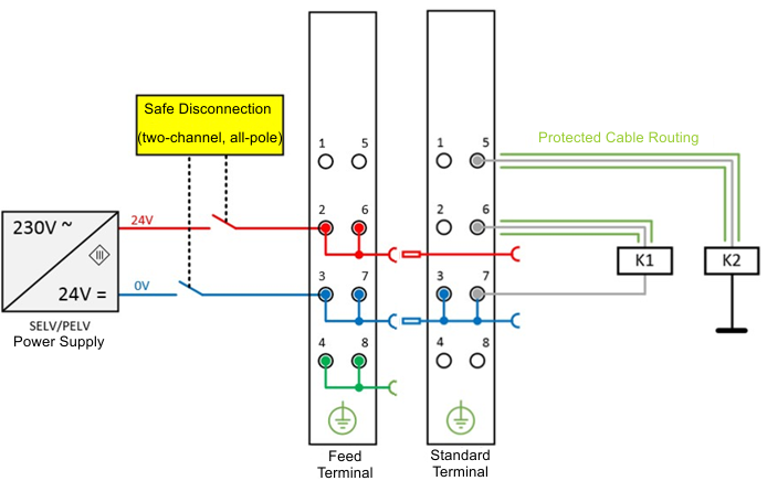 Fig.3: Excluding a short-circuit fault by protecting cables
Summary of safety levels
Feedback prevention measures | DIN EN ISO 13849-1 | IEC 61508 | EN 62061 |
|---|---|---|---|
Cable short-circuit fault exclusion
| max. Cat. 4 PL e | max. SIL3 | max. SIL2* |
Ground return and all-pole disconnection | max. SIL3 |
| |
Please follow the instructions for operating interference-free terminals!
|
