Connection and LEDs
| |
Risk of injury through electric shock and damage to the device! Bring the bus terminal system into a safe, de-energized state before beginning to mount, disassemble, or wire the bus terminals! |

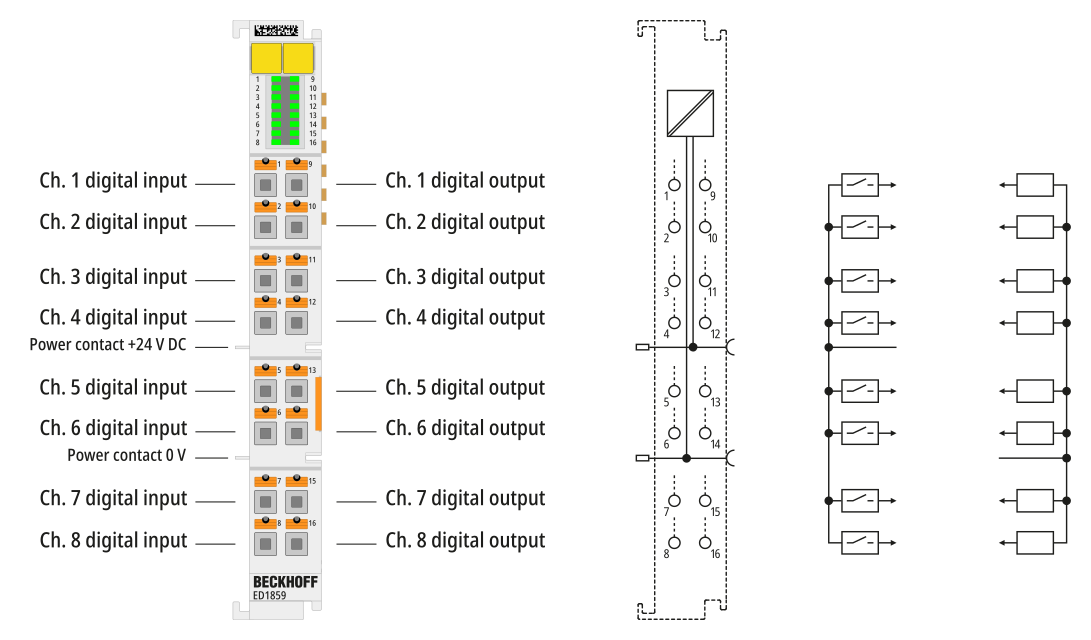
Connection
Terminal point | Description | |
|---|---|---|
Abbreviation | No. | |
Ch1 DI | 1 | Digital input 1 |
… | … | .. |
Ch8 DI | 8 | Digital input 8 |
Ch1 DO | 9 | Digital output 1 |
… | … | .. |
Ch8 DO | 16 | Digital output 8 |
LEDs
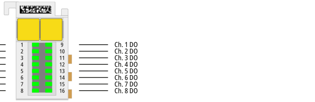
Name | No. | Color | Meaning | |
|---|---|---|---|---|
Input status | 1…8 | green | off | Signal voltage “0” (-3 V…5 V) |
on | Signal voltage “1” (11 V…30 V) | |||
Output status | 9…16 | green | off | No output signal |
on | 24 V DC output signal at the respective output | |||