Standard objects
Standard objects (0x1000-0x1FFF)
The standard objects have the same meaning for all EtherCAT slaves.
Index 1000 Device type
|
Index |
Name |
Meaning |
Data type |
Flags |
Default |
|---|---|---|---|---|---|
|
1000:0 |
Device type |
Device type of the EtherCAT slave: The low word contains the CoE profile used (5001). The high word contains the module profile according to the modular device profile. |
UINT32 |
RO |
0x00651389 (6624137dec) |
Index 1008 Device name
Index | Name | Meaning | Data type | Flags | Default |
|---|---|---|---|---|---|
1008:0 | Device name | Device name of the EtherCAT slave | STRING | RO | ED1837 |
Index 1009 Hardware version
|
Index |
Name |
Meaning |
Data type |
Flags |
Default |
|---|---|---|---|---|---|
|
1009:0 |
Hardware version |
Hardware version des EtherCAT slaves |
STRING |
RO |
|
Index 100A Software version
|
Index |
Name |
Meaning |
Data type |
Flags |
Default |
|---|---|---|---|---|---|
|
100A:0 |
Software version |
Firmware version des EtherCAT slaves |
STRING |
RO |
00 |
Index 100B Bootloader version
Index | Name | Meaning | Data type | Flags | Default |
|---|---|---|---|---|---|
100B:0 | Bootloader version | Bootloader version | STRING | RO | n/a |
Index 1018 Identity
Index | Name | Meaning | Data type | Flags | Default |
|---|---|---|---|---|---|
1018:0 | Identity | information for identifying the slave | UINT8 | RO | 0x04 (4dec) |
1018:01 | Vendor ID | vendor ID of the EtherCAT slave | UINT32 | RO | 0x00000002 (2dec) |
1018:02 | Product code | product code of the EtherCAT slave | UINT32 | RO | see below* |
1018:03 | Revision | Revision number of the EtherCAT slave; the low word (bit 0–15) indicates the special terminal number, the high word (bit 16–31) refers to the device description | UINT32 | RO | 0x00000000 (0dec) |
1018:04 | Serial number | Serial number of the EtherCAT slave; the low byte (bit 0–7) of the low word contains the year of production, the high byte (bit 8–15) of the low word contains the week of production, the high word (bit 16–31) is 0 | UINT32 | RO | 0x00000000 (0dec) |
* ED1837: 0x072D1052 (120393810dec); ED1839: 0x072F1052 (120524882dec) | |||||
Index 1020 Device Statistics
Index | Name | Meaning | Data type | Flags | Default |
|---|---|---|---|---|---|
1020:0 | Device Statistics | max. subindex | UINT8 | RO | 0x03 (3dec) |
1020:01 | Time since power on | Operating time since last power-on [s] | UINT32 | RO | 0x00000000 (0dec) |
1020:02 | Total time powered | Total operating time [s] | UINT32 | RO | 0x00000000 (0dec) |
1020:03 | Number of power cycles | Number of power cycles | UINT32 | RO | 0x00000000 (0dec) |
Index 10E2 Manufacturer-specific Identification Code
Index | Name | Meaning | Data type | Flags | Default |
|---|---|---|---|---|---|
10E2:0 | Manufacturer-specific Identification Code | Manufacturer-specific Identification Code | UINT8 | RO | 0x01 (1dec) |
10E2:01 | SubIndex 001 | reserved | STRING | RO |
|
Index 10F0 Backup parameter handling
|
Index |
Name |
Meaning |
Data type |
Flags |
Default |
|---|---|---|---|---|---|
|
10F0:0 |
Backup parameter handling |
Information for standardized loading and saving of backup entries |
UINT8 |
RO |
0x01 (1dec) |
|
10F0:01 |
Checksum |
Checksum across all backup entries of the EtherCAT slave |
UINT32 |
RO |
0x00000000 (0dec) |
Index 1App DIP TxPDO Map Inputs
Index (hex) | Name | Meaning | Data type | Flags | Default |
|---|---|---|---|---|---|
1App:0 | DIP TxPDO-Map Inputs | PDO Mapping TxPDO | UINT8 | RO | 0x01 (1dec) |
1App:01 | SubIndex 001 | PDO Mapping entry no. 1 (object 0x6pp0 (DIP Inputs Ch.1), entry 0x01 (Input)) | UINT32 | RO | 0x6000:01, 1 |
ED1837: Ch.1–Ch.32 (00 <= pp <= 1F) ED1839: Ch.1–Ch.16 (00 <= pp <= 0F) | |||||
Index 1C00 Sync manager type
|
Index |
Name |
Meaning |
Data type |
Flags |
Default |
|---|---|---|---|---|---|
|
1C00:0 |
Sync manager type |
Using the Sync Managers |
UINT8 |
RO |
0x04 (4dec) |
|
1C00:01 |
SubIndex 001 |
Sync Manager Type Channel 1: Mailbox Write |
UINT8 |
RO |
0x01 (1dec) |
|
1C00:02 |
SubIndex 002 |
Sync Manager Type Channel 2: Mailbox Read |
UINT8 |
RO |
0x02 (2dec) |
|
1C00:03 |
SubIndex 003 |
Sync Manager Type Channel 3: Process Data Write (Outputs) |
UINT8 |
RO |
0x03 (3dec) |
|
1C00:04 |
SubIndex 004 |
Sync Manager Type Channel 4: Process Data Read (Inputs) |
UINT8 |
RO |
0x04 (4dec) |
Index 1C12 RxPDO assign
|
Index |
Name |
Meaning |
Data type |
Flags |
Default |
|---|---|---|---|---|---|
|
1C12:0 |
RxPDO assign |
PDO Assign Outputs |
UINT8 |
RO |
0x00 (0dec) |
Index 1C13 TxPDO assign, ED1837
Index (hex) | Name | Meaning | Data type | Flags | Default |
|---|---|---|---|---|---|
1C13:0 | TxPDO assign | PDO Assign Inputs | UINT8 | RO | 0x20 (32dec) |
1C13:01 | SubIndex 001 | allocated TxPDO no. 1 (contains the index of the associated TxPDO mapping object) | UINT16 | RO | 0x1A00 (6656dec) |
1C13:02 | SubIndex 002 | allocated TxPDO no. 2 (contains the index of the associated TxPDO mapping object) | UINT16 | RO | 0x1A01 (6657dec) |
… | … | … | ... | … | … |
1C13:1F | SubIndex 031 | allocated TxPDO no. 31 (contains the index of the associated TxPDO mapping object) | UINT16 | RO | 0x1A1E (6686dec) |
1C13:20 | SubIndex 032 | allocated TxPDO no. 32 (contains the index of the associated TxPDO mapping object) | UINT16 | RO | 0x1A1F (6687dec) |
Index 1C13 TxPDO assign, ED1839
Index (hex) | Name | Meaning | Data type | Flags | Default |
|---|---|---|---|---|---|
1C13:0 | TxPDO assign | PDO Assign Inputs | UINT8 | RO | 0x10 (16dec) |
1C13:01 | SubIndex 001 | allocated TxPDO no. 1 (contains the index of the associated TxPDO mapping object) | UINT16 | RO | 0x1A00 (6656dec) |
1C13:02 | SubIndex 002 | allocated TxPDO no. 2 (contains the index of the associated TxPDO mapping object) | UINT16 | RO | 0x1A01 (6657dec) |
… | … | … | ... | … | … |
1C13:0F | SubIndex 031 | allocated TxPDO no. 15 (contains the index of the associated TxPDO mapping object) | UINT16 | RO | 0x1A0E (6670dec) |
1C13:10 | SubIndex 032 | allocated TxPDO no. 16 (contains the index of the associated TxPDO mapping object) | UINT16 | RO | 0x1A0F (6671dec) |
Index 1C33 SM input parameter
Index | Name | Meaning | Data type | Flags | Default |
|---|---|---|---|---|---|
1C33:0 | SM input parameter | Synchronization parameters for the inputs | UINT8 | RO | 0x20 (32dec) |
1C33:01 | Sync mode | Current synchronization mode:
34: synchronous with SM 2 event (outputs available) | UINT16 | RW | 0x0000 (0dec) |
1C33:02 | Cycle time | Cycle time (in ns):
DC mode: SYNC0/SYNC1 Cycle Time | UINT32 | RW | 0x000186A0 (100000dec) |
1C33:03 | Shift time | time between SYNC0 event and reading of the inputs (in ns, DC mode only) | UINT32 | RO | 0x00000000 (0dec) |
1C33:04 | Sync modes supported | Supported synchronization modes:
bit 14 = 1: dynamic times (measurement through writing of 1C32:08 or 1C33:08) | UINT16 | RO | 0x0001 (1dec) |
1C33:05 | Minimum cycle time | Minimum cycle time (in ns) | UINT32 | RO | 0x000186A0 (100000dec) |
1C33:06 | Calc and copy time | Time between reading of the inputs and the inputs being available for the master (in ns, DC mode only) | UINT32 | RO | 0x00000000 (0dec) |
1C33:07 | Minimum delay time | Min. time between SYNC1 event and reading of the inputs (in ns, DC mode only) | UINT32 | RO | 0x00000000 (0dec) |
1C33:08 | Get Cycle Time |
Entries 1C32:03, 1C32:05, 1C32:06, 1C32:09, 1C33:03, 1C33:06, 1C33:09 are updated with the maximum measured values. For a subsequent measurement, the measured values are reset | UINT16 | RW | 0x0000 (0dec) |
1C33:09 | Maximum delay time | Time between SYNC1 event and reading of the inputs (in ns, DC mode only) | UINT32 | RO | 0x00000000 (0dec) |
1C33:0B | SM event missed counter | Number of missed SM events in OPERATIONAL (DC mode only) | UINT16 | RO | 0x0000 (0dec) |
1C33:0C | Cycle exceeded counter | Number of cycle time violations in OPERATIONAL (cycle was not completed on time or the next cycle started too early) | UINT16 | RO | 0x0000 (0dec) |
1C33:0D | Shift too short counter | Number of times that the interval between SYNC0 and SYNC1 event was too short (DC mode only) | UINT16 | RO | 0x0000 (0dec) |
1C33:20 | Sync error | The synchronization was not correct in the last cycle (outputs were output too late; DC Mode only) | BOOLEAN | RO | 0x00 (0dec) |
Index F000 Modular Device Profile
Index | Name | Meaning | Data type | Flags | Default |
|---|---|---|---|---|---|
F000:0 | Modular Device Profile | general information for the Modular Device Profile | UINT8 | RO | 0x02 (2dec) |
F000:01 | Index distance | index distance of the objects of the individual channels | UINT16 | RO | 0x0010 (16dec) |
F000:02 | Maximum number of modules | number of channels | UINT16 | RO | ED1837: ED1839: |
Index F001 Code word
Index | Name | Meaning | Data type | Flags | Default |
|---|---|---|---|---|---|
F008:0 | Code word | Reserved | UINT32 | RW | 0x00000000 (0dec) |
Index F081 Download revision
Index | Name | Meaning | Data type | Flags | Default |
|---|---|---|---|---|---|
F081:0 | Download revision | max. subindex | UINT8 | RO | 0x01 (1dec) |
F081:01 | Revision number | The subindex 0xF081:01 (Download revision) describes the revision level of the module. | UINT32 | RW |
|
 | Download revision in the startup list Individual terminals/modules automatically generate the entry from object 0xF081:01 in the startup list (see figure “Download revision in the startup list”). |
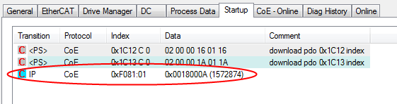 Fig.15: Download revision in the startup list