Mounting rail installation
| |
Risk of injury through electric shock and damage to the device! Bring the bus terminal system into a safe, de-energized state before beginning to mount, disassemble, or wire the bus terminals! |

The bus terminal system is designed for installation in a control cabinet or junction box.
Installation
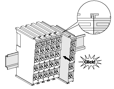
The bus couplers and bus terminals are attached to commercially available 35 mm mounting rails (DIN rail according to EN 60715) by applying slight pressure:
- First attach the fieldbus coupler to the mounting rail.
- The bus terminals are now attached on the right-hand side of the fieldbus coupler. To do this, connect the components with the slot and key and push the terminals against the mounting rail until the latch audibly engages on the mounting rail.
If you snap the terminals onto the mounting rail first and then push them next to each other without the slot and key engaging, no functional connection will be established! When correctly assembled, no significant gap should be visible between the housing units.
 | Fastening the mounting rails The locking mechanism of the terminals and couplers protrudes into the profile of the mounting rail. When installing the components, make sure that the locking mechanism doesn't come into conflict with the fixing bolts of the mounting rail. When fastening mounting rails with a height of 7.5 mm under the terminals and couplers, use flat fastening components such as countersunk head screws or blind rivets. |
Notice | |
Earth the mounting rail! Make sure the mounting rail is properly earthed. |
Connections within a bus terminal block
The electric connections between the bus coupler and the bus terminals are made automatically by joining the components:
- The six spring-loaded contacts of the E-bus/K-bus deal with the data transfer and the supply of the bus terminal electronics.
- The power contacts deal with the supply for the field electronics and thus represent a supply rail within the bus terminal block. The power contacts are supplied via terminal points on the bus coupler (up to 24 V) or via power supply terminals for higher voltages.
| Power contacts When configuring a bus terminal block, note the contact assignments of the individual bus terminals, as some types
|
Power contact ⏚
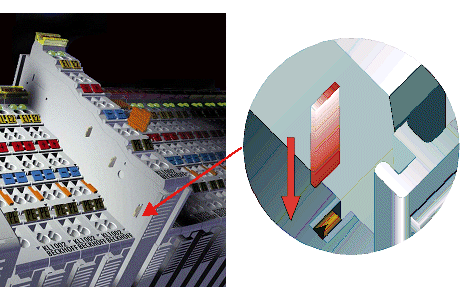
The power contact marked ⏚ (ground connection in accordance with IEC 60417-5017) can be used as a ground. For safety reasons this contact mates first when plugging together, and can ground short-circuit currents of up to 125 A.
| |
Risk of injury from electric shock! The power contact marked ⏚ may not be used for other potentials! |
Notice | |
Risk of damage to the device Note that, for electromagnetic compatibility, the earth contacts are capacitatively coupled to the mounting rail. This may lead to incorrect results during insulation testing or to damage to the terminal (e.g. disruptive discharge to the earth line during insulation testing of a consumer with a rated voltage of 230 V). For insulation testing, disconnect the earth supply line at the bus coupler or the power supply terminal! In order to decouple further supply points for testing, these power supply terminals can be released and pulled at least 10 mm from the group of terminals. |
Disassembly
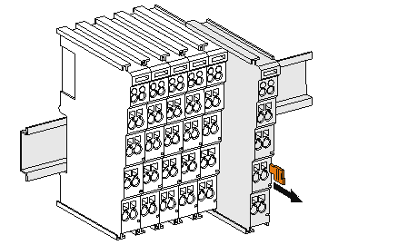
Each terminal is secured by a lock on the mounting rail, which must be released for disassembly:
- Pull down the terminal at its orange-colored straps from the mounting rail by approx. 1 cm. The rail locking of this terminal is automatically released, and you can now pull the terminal out of the bus terminal block with little effort.
- To do this, grasp the unlocked terminal simultaneously at the top and bottom of the housing surfaces with your thumb and index finger and pull it out of the bus terminal block.