EAP telegram structure
An EAP telegram can be transmitted by Ethernet (Ethertype = 0x88A4, corresponds to the EtherCAT protocol) or by UDP/IP (UDP port 0x88A4). If EAP is based on the EtherCAT protocol, the EAP-specific telegram parts are embedded in the user data of the EtherCAT protocol.
The EAP telegram consists of a Process Data Frame Header and one or more ProcessData (PD). A PD is the main unit in the exchange of data via EAP. A PD is composed of the so-called PDO Header and at least one Process Variable (PV). On the whole, the Process Variables of a PD form the ProcessDataObject (PDO). See the following illustration.
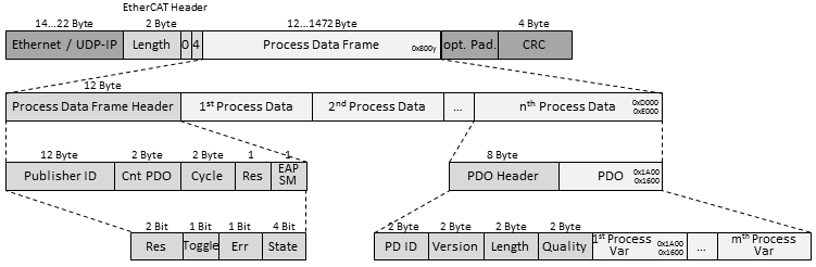
The Process Data Frame Header
The Process Data Frame Header consists of five fields (see lines 2 and 3 in the illustration above). The latter field (EAP SM) extends the NWV telegram of twincat 2 with regard to contents.This field contains among other things information about the current state of the EAP device.
Publisher ID
The sender of a telegram is identified on the basis of the Publisher ID. It contains the AMS NetID of the sender. If a receiver is configured so that it only processes telegrams from a certain sender, a check is carried out on the basis of the Publisher ID field as to whether the EAP telegram originated from this sender.
Cnt PDO
This field contains the number of ProcessData contained in the telegram, so that the receiver can fully process the telegram.
Cycle
The value of this field is incremented with each task cycle of the sender. On the receiving side the contents of this field can be used as a sequential number in order, for example, to check whether a telegram has been lost. This field should be monitored on the server side in Polled Data Exchange mode.
Res
reserved for future extensions.
EAP SM
This field is composed of 4 subentries.
- Res: reserved for future extensions.
- Toggle: This bit is toggled for each new EAP telegram.
- Err: This field indicates whether an error has occurred with the EAP State Machine.
- State: This field contains the value for the current state of the EAP State Machine.
- 1 : Init
- 2 : Pre-Operational
- 4 : Safe-Operational
- 8 : Operational
Values other than these are not allowed
The PDO Header
The PDO Header consists of 4 fields, each of which has a data length of 2 bytes (see lines 3 and 4 in the illustration above).
PD ID
The PD ID (16-bit) serves as the global identification of the EAP variables and should be unique in the network.
 | Selection of the ProcessData Identifier (PD ID) In order to achieve unambiguous allocation we recommend using different IDs for each data communication between connected PCs. |
Version
A version number can be entered for the PD in this field. The influence that the version has on the EAP communication is explained in the Network protocols section of the chapter Communication methods. The version number should be consistently increased if at least one of the following changes is made to ProcessData.
- The data length of the ProcessData is changed.
- The data type of a variable of the ProcessData is changed.
- The order of the variables in a PDO is changed.
Length
This field contains the length of the ProcessData in bytes. The length of the Process Data Header itself is not included.
Quality
The value of this field shows the age of the ProcessData in the unit [100 µs] if the value lies between 0x0 and 0xEFFF. A value greater than or equal to 0xF000 means that the ProcessData is invalid.
The Process Variable (PV)
The Process Variable contains the actual data to be transmitted (see Process Var in line 4 of the first illustration above). The data length of a PV may only be so large that the entire EAP telegram is not larger than 1514 bytes.
| Calculation of the size of an EAP telegram The sum of the lengths of all headers and all publisher variables may not exceed the limit of 1514 bytes. The EAP telegram shown (see following illustration) has a total size of |
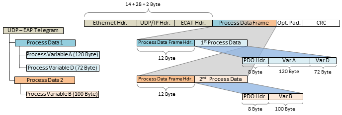
(This calculation includes 28 bytes for the UDP/IP Hdr. The 28 bytes are available for data in pure Ethernet communication.)
Data representation on different platforms
Note that both simple and complex data (WORD, ARRAYs, REAL, STRING, user-defined structures) are represented internally in a different manner on different platforms. x86 platforms use byte-alignment, others (Arm®) 2-byte or 4-byte alignment.
This means that if a complex structure is created in both an x86/PC PLC project and an Arm® PLC project, they can each have a different effective size and a different internal structure.
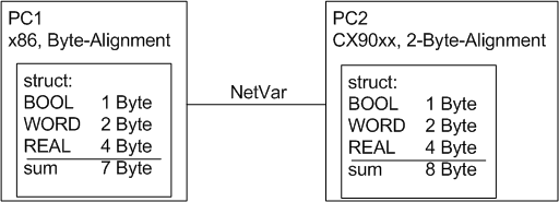
In the example (see illustration above) the structure in PC2 is larger than in PC1. Not only that, the word and real variables don't match, since a variable can begin at any byte position in PC1 but only at any even-numbered byte position in PC2.
It is recommended to observe the following rules when assembling structures so that no size differences are caused by the alignment:
- firstly, all 4-byte variables (must lie at an address that is divisible by 4)
- then all 2-byte variables (must lie at an address that is divisible by 2)
- then all 1-byte variables
Further recommendation:
- If the data type STRING(x) is used in a PLC, the null termination of the string also belongs to the string itself, so that x+1 must be divisible by 4. Otherwise there is no 4-byte alignment.
- The above rules also apply to substructures.
Other information can be found in the Beckhoff information system under structures or alignment.
NOTICE | ||
Use of Bus Terminal Controllers (BCxxxx, BXxxxx) Floating point numbers (data type REAL) cannot be transmitted to Bus Terminal controllers (BCxxxx, BXxxxx), since the representation of a floating point number on a Bus Terminal controller differs from that on an x86 platform. | ||