Jerk-limited standard acceleration profile
Both for axes in the contouring combination and for independent axes, a jerk-limited acceleration with a trapezoidal or a sine-square profile can be chosen. The parameters are defined equally for both profiles in relation to each specific axis. Contrary to the trapezoidal profile, the sine-square profile enables softer acceleration and deceleration.
In the case of jerk-limited acceleration, the contouring motion is guided so that the axis-specific accelerations do not suffer any abrupt changes.
For HSC-contouring a specific jerk limited slope can be activated, this slope has a optimized block global acceleration planning.
These profiles must be used for machine mechanics that are critical in terms of vibrations. The ramp times for building up and reducing acceleration should only be set as high as necessary and as low possible because these parameters have a considerable influence on the positioning times.
Segments of profile
The jerk-limited acceleration profile can be presented in seven segments (Figure1-3).
I | Speed increase with increasing acceleration to a maximum acceleration value within a specified time |
II | Speed increase with constant acceleration |
III | Speed increase with decreasing acceleration down to the acceleration value 0 within a specified time |
IV | Phase of constant speed, acceleration 0 |
V | Speed decrease with increasing deceleration to a maximum braking acceleration value within a specified time |
VI | Speed decrease with constant deceleration |
VII | Speed decrease with decreasing deceleration down to the braking acceleration value 0 within a specified time |
The parameters in segments I, III, V and VII determine the axis jerk that is caused by the acceleration profile.
Advantage
The advantages of the jerk-limited acceleration profiles are:
- Better use of available machine dynamics (e.g. positioning in the rapid traversing mode)
- Reduced wear and tear of the mechanical systems by avoiding impacts
- Low excitation of vibrations
- Improved possibility of defining the parameters of contour-improving processes (e.g. feed forward control)
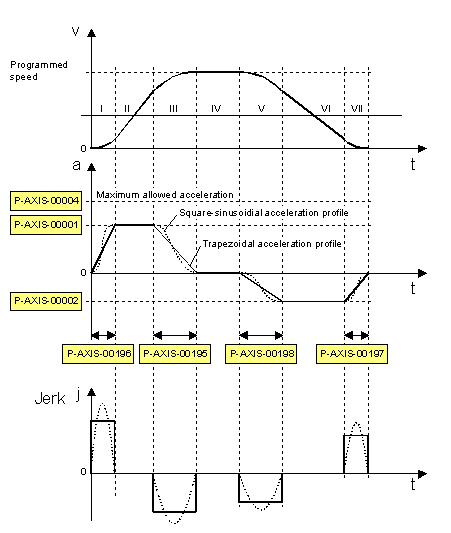 Fig.3: Parameters for jerk-limited acceleration profile
Parameterization
The axis-specific acceleration ramps of the jerk-limited acceleration profiles are defined by specifying maximum acceleration and a maximum ramp time. Figure1-3 shows the profiles of the speed, acceleration, and jerk with the corresponding parameters.
The maximum acceleration at increasing speed is set with P-AXIS-00001. At decreasing speed, the maximum deceleration must be set via the P-AXIS-00002 parameter. The maximum ramp times are defined by means of the P-AXIS-00195, P-AXIS-00196, P-AXIS-00197 and P-AXIS-00198 parameters.
An individual acceleration ramp can be set for each acceleration and deceleration phase with the parameters listed.
When defining the parameters of the ramp time, you must consider the fact that the jerk-limited acceleration profile develops towards the abrupt acceleration profile in the event of ramp times less than the CNC cycle time.
Parameterization for rapid traversing (G00)
The jerk-limited acceleration profile with steeper acceleration ramps can be defined for motions in the rapid traversing mode (G00). All acceleration ramps (segments: I, III, V, VII) are defined with the maximum acceleration P-AXIS-00004 and the maximum ramp time P-AXIS-00200 (Figure1-4).
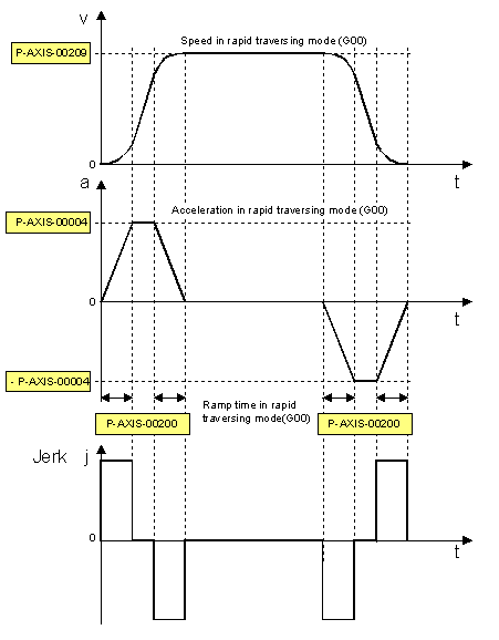 Fig.4: Parameters for jerk limiting in the rapid traversing mode (G00)
Parameterization for feed hold
The acceleration ramps (segments: V, VII) are parameterized with the maximum acceleration P-AXIS-00053 and the maximum ramp time P-AXIS-00081 for fast braking from feed stop to standstill.
The influence of the channel parameter P-CHAN-00097 must be taken into account (see Chapter Control flags).