Diagnostic LEDs
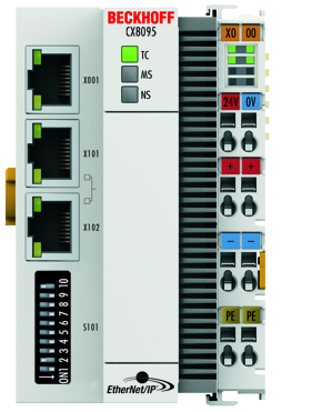
Ethernet interface X001
|
Interface X001 |
Ethernet (CX8095) |
Meaning |
|---|---|---|
|
LED green |
on |
Link present |
|
LED yellow |
flashing |
Activity |
Ethernet interface X101 and X102
|
Interface X101-102 |
Ethernet (CX8095) |
Meaning |
|---|---|---|
|
LED green |
flashing |
Activity |
|
LED yellow |
is not used |
- |
LED coupler
|
Labelling |
Meaning |
Color |
Meaning |
|---|---|---|---|
|
TC |
Displays the TwinCAT mode |
red |
TwinCAT in Stop |
|
Green |
TwinCAT in Running Mode | ||
|
Blue |
TwinCAT in Config Mode |
|
Labelling |
Color green |
Color red |
Meaning |
|---|---|---|---|
|
MS |
off |
off |
no EtherNet/IP slave configuration on the CX8095. |
|
on |
off |
All configured IO assemblies are in data exchange with the EtherNet/IP master. All connections are in the run state (cyclic exchange of valid process data). | |
|
fast blinking |
off |
Watchdog error, EtherNet/IP scanner connection lost. | |
|
off (1 s) |
off |
No connection or faulty connection to the scanner. | |
|
flashes (400 ms) |
off |
One of the EtherNet/IP slaves has no valid IO assembly configuration. | |
|
off |
off (1 s) |
A general error occurred with the EtherNet/IP slave. | |
|
off |
on |
Internal error. |
|
Labelling |
Color green |
Color red |
Meaning |
|---|---|---|---|
|
NS |
off |
off |
No link detected. |
|
on |
off |
The CX8095 has detected a link and was configured. | |
|
flashes (400 ms) |
off |
At least one Ethernet port has an active link and a configured EtherNet/IP Slave interface has no valid IP address configured. | |
|
off (1 s) |
off |
All configured EtherNet/IP slaves have a valid IP address configuration. UDP and TCP Layer was initialized. | |
|
off |
on |
Internal error. | |
|
off |
off (1 s) |
A general error occurred with the EtherNet/IP slave. |
LED power supply terminal
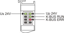
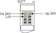
Operation with K-bus terminals Operation with E-bus terminals
|
Display LED |
Description |
Meaning |
|---|---|---|
|
1 Us 24 V (top left, 1st row) |
CX80xx supply voltage |
connected to -24 V |
|
2 Up 24 V (top right, 1st row) |
Power contacts supply voltage |
connected to -24 V |
|
3 L/A (left center, 2nd row) |
EtherCAT LED |
flashing green: EtherCAT communication active |
|
4 K-BUS RUN (right center, 2nd row) |
K-bus LED RUN |
Lights up green: K-bus running, everything OK |
|
6 K-BUS ERR (bottom right, 3rd row) |
K-bus LED ERR |
Lights up red: K-bus error - see K-bus error code |
K-bus error code
|
Error code |
Error code argument |
Description |
Remedy |
|---|---|---|---|
|
Persistent, continuous flashing |
|
EMC problems |
|
|
3 pulses |
0 |
K-bus command error |
- No Bus Terminal inserted |
|
4 pulses |
0 |
K-Bus data error, break behind the Bus Coupler |
Check whether the n+1 Bus Terminal is correctly connected; replace if necessary. |
|
n |
Break behind Bus Terminal n |
Check whether the bus end terminal 9010 is connected. | |
|
5 pulses |
n |
K-bus error in register communication with Bus Terminal n |
Exchange the nth bus terminal |
|
6 pulses |
0 |
Error at initialization |
Exchange Bus Coupler |
|
1 |
Internal data error |
Perform a hardware reset on the Bus Coupler (switch off and on again) | |
|
8 |
Internal data error |
Perform a hardware reset on the Bus Coupler (switch off and on again) | |
|
7 pulses |
0 |
Process data lengths do not correspond to the configuration |
Check the Bus Terminals for the configured Bus Terminals |
|
1..n |
K-bus reset failed |
Check the Bus Terminals |