LED displays
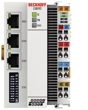
Ethernet interface X001
Interface X001 | Ethernet (CX8093) | Meaning |
|---|---|---|
LED green | on | Link present |
LED yellow | flashing | Activity |
Ethernet interface X101/102
Interface X001/X002 | Ethernet (CX8093) | Meaning |
|---|---|---|
LED green | on | Link available/activity |
LED yellow | is not used | - |
LED coupler
Labelling | Meaning | Colour | Meaning |
|---|---|---|---|
RUN | Indicates the status of the coupler | red | TwinCAT is in "stop" mode |
Green | TwinCAT is in "run" mode | ||
Blue (If red DIP switch 1 is set to on when starting the coupler) | TwinCAT is in "config" mode |
LED PN * | PROFINET Status | Meaning | |
|---|---|---|---|
green | red | ||
Power On | off | 200 ms flashing | Start-up phase |
No name | 200 ms flashing | off | no PROFINET name |
No IP | 1 sec off, 200 ms on | off | No IP address |
Run | on | off | OK |
LED DIAG * | PROFINET diagnosis | Meaning | |
|---|---|---|---|
green | red | ||
Flashing, PN controller identification | 500 ms | 500 ms | The PN controller is transmitting an identification signal |
No AR established | off | 200 ms flashing | The establishment of a connection with the controller has not been completed |
Device is in IO exchange | 1 s off 200, ms on | off | Problem with establishment of a connection or nominal and actual configuration differ |
Device is in IO exchange but provider is in stop | 200 ms | off | Coupler is in data exchange, but PLC is in stop |
Device is in IO exchange | on | off | OK |
* ) If a virtual PROFINET device has been projected, this is also signalled by the LEDs in the event of an error. The real device always has the higher priority; if it is OK the status of the virtual device is displayed.
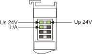
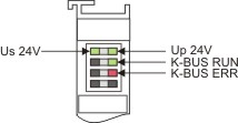
LED power supply terminal
|
|
Operation with E-bus terminals | Operation with K-bus terminals |
Display LED | Description | Meaning |
|---|---|---|
1 Us 24 V (top left, 1st row) | CX80xx supply voltage | connected to -24 V |
2 Up 24 V (top right, 1st row) | Power contacts supply voltage | connected to -24 V |
3 L/A (left centre, 2nd row) | EtherCAT LED | flashing green: EtherCAT communication active |
4 K-BUS RUN (right centre, 2nd row) | K-bus LED RUN | Lights up green: K-bus running, everything OK |
6 K-BUS ERR (bottom right, 3rd row) | K-bus LED ERR | Lights up red: K-bus error - see K-bus error code |
K-bus error code
Error code | Error code argument | Description | Remedy |
|---|---|---|---|
Persistent, continuous flashing |
| EMC problems |
|
3 pulses | 0 | K-bus command error |
|
4 pulses | 0 | K-Bus data error, break behind the Bus Coupler | Check whether the n+1 Bus Terminal is correctly connected; replace if necessary. |
n | Break behind Bus Terminal n | Check whether the Bus End Terminal 9010 is connected. | |
5 pulses | n | K-Bus error in register communication with Bus Terminal n | Exchange the nth bus terminal |
6 pulses | 0 | Error at initialisation | Exchange Bus Coupler |
1 | Internal data error | Perform a hardware reset on the Bus Coupler (switch off and on again) | |
8 | Internal data error | Perform a hardware reset on the Bus Coupler (switch off and on again) | |
7 pulses | 0 | Process data lengths do not correspond to the configuration | Check the Bus Terminals for the configured Bus Terminals |
1..n | K-bus reset failed | Check the Bus Terminals |