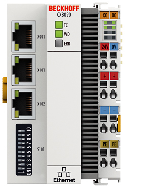
Diagnostic LEDs
Ethernet interface X001
|
Interface X001 |
Ethernet (CX8090, CX8091) |
Meaning |
|---|---|---|
|
LED green |
on |
Link present |
|
LED yellow |
flashing |
Activity |
Ethernet interface X101 and X102
|
Interface X101-102 |
Ethernet (CX8090, CX8091) |
Meaning |
|---|---|---|
|
LED green |
flashing |
Activity |
|
LED yellow |
is not used |
- |
LED coupler
|
Labelling |
Meaning |
Colour |
Meaning |
|---|---|---|---|
|
TC |
Displays the TwinCAT mode |
red |
TwinCAT in Stop |
|
green |
TwinCAT in Running Mode | ||
|
Blue |
TwinCAT in Config Mode | ||
|
WD* |
no function |
- |
- |
|
ERR* |
Error or Boot Diagnosis LED |
red when switching on |
Software is being loaded |
|
off |
Everything OK |
* The WD and ERR LED can be set and used by function block.
LED power supply terminal
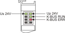
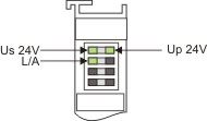
Operation with K-bus terminals Operation with E-bus terminals
|
Display LED |
Description |
Meaning |
|---|---|---|
|
1 Us 24 V (top left, 1st row) |
CX80xx supply voltage |
connected to -24 V |
|
2 Up 24 V (top right, 1st row) |
Power contacts supply voltage |
connected to -24 V |
|
3 L/A (left centre, 2nd row) |
EtherCAT LED |
flashing green: EtherCAT communication active |
|
4 K-BUS RUN (right centre, 2nd row) |
K-bus LED RUN |
Lights up green: K-bus running, everything OK |
|
6 K-BUS ERR (bottom right, 3rd row) |
K-bus LED ERR |
Lights up red: K-bus error - see K-bus error code |
K-bus error code
|
Error code |
Error code argument |
Description |
Remedy |
|---|---|---|---|
|
Persistent, continuous flashing |
|
EMC problems |
|
|
3 pulses |
0 |
K-Bus command error |
- No Bus Terminal inserted |
|
4 pulses |
0 |
K-Bus data error, break behind the Bus Coupler |
Check whether the n+1 Bus Terminal is correctly connected; replace if necessary. |
|
n |
Break behind Bus Terminal n |
Check whether the Bus End Terminal 9010 is connected. | |
|
5 pulses |
n |
K-Bus error in register communication with Bus Terminal n |
Exchange the nth bus terminal |
|
6 pulses |
0 |
Error at initialization |
Exchange Bus Coupler |
|
1 |
Internal data error |
Perform a hardware reset on the Bus Coupler (switch off and on again) | |
|
8 |
Internal data error |
Perform a hardware reset on the Bus Coupler (switch off and on again) | |
|
7 pulses |
0 |
Process data length is not correct |
Check the configuration and the K-Bus terminals |
|
1..n |
K-Bus Reset error |
Check the K-Bus terminals |