Programming of the RS232/485 interface
In KL6xx1 mode, any serial protocols can be implemented. To this end, configure the interface as KL6xx1 mode in the System Manager.
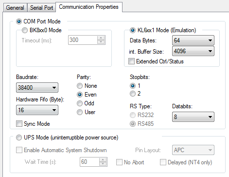
This mode behaves like the serial interface terminals from Beckhoff. It only means that the programming and the interface is similar to a serial interface. The Beckhoff supplement blocks (such as ModbusRTU, COMLIB, ...) of the serial interface usually offer the 64-byte mode for the PC interface.
Alternatively, you can operate and program the interface yourself.
The data structure consists of a control and status word (2 bytes) and a data array. The control byte is written by the PLC program and acknowledges the sending of data with the TR bit. Toggling the bit (edge change) results in sending of the number of data (length of the data OL bits to be written) from the interface. The RA bit acknowledges that the receive data were read. This enables the interface to detect that it can copy new data into the data array. The status word indicates how many data are valid. The Reset bit (IR Control.2, positive edge) clears the buffers and resets the interface. The interface also acknowledges the command in the status word with a Reset bit (IA Status.2). Then set the Reset bit (IR Control.2) to False again.
|
Bit |
15 |
14 |
13 |
12 |
11 |
10 |
09 |
08 |
07 |
06 |
05 |
04 |
03 |
02 |
01 |
00 |
|
Name |
Length of data to be written (OL bits) |
Reserve |
IR |
RA |
TR | |||||||||||
Legend
|
Bit |
Name |
Comment | |
|---|---|---|---|
|
CW.3 |
Reserved |
- |
- |
|
CW.2 |
IR |
1bin |
The controller requests terminal for initialization. The send and receive functions are blocked, the FIFO indicators are reset, and the interface is again initialized with the value. The interface acknowledges completion of the initialization via bit SW.2 (IA). |
|
0bin |
The controller once again requests the interface to prepare for serial data exchange. | ||
|
CW.1 |
RA |
toggle |
The controller acknowledges receipt of data by changing the state of this bit. Only then new data can be transferred from the interface to the controller. |
|
CW.0 |
TR |
toggle |
Via a change of state of this bit the controller notifies the interface that the DataOut bytes contain the number of bytes indicated via the OL bits. The interface acknowledges receipt of the data in the status byte via a change of state of word SW.0 (TA). Only now new data can be transferred from the controller to the interface. |
|
Bit |
15 |
14 |
13 |
12 |
11 |
10 |
09 |
08 |
07 |
06 |
05 |
04 |
03 |
02 |
01 |
00 |
|
Name |
Length of data in the buffer ((IL bits) |
BUF_F |
IA |
RR |
TA | |||||||||||
Legend
|
Bit |
Name |
Comment | |
|---|---|---|---|
|
SW.3 |
BUF_F (buffer full) |
1bin |
The reception FIFO is full. All further incoming data will be lost! |
|
SW.2 |
IA |
1bin |
Initialization was completed by the interface. |
|
0bin |
The interface is ready again for serial data exchange. | ||
|
SW.1 |
RR |
toggle |
Via a change of state of this bit the interface notifies the controller that the DataIn bytes contain the number of bytes indicated via the IL bits. The controller has to acknowledge receipt of the data in the control word via a change of state of bit CW.1 (RA). Only then new data can be transferred from the interface to the controller. |
|
SW.0 |
TA |
toggle |
The interface acknowledges receipt of data by changing the state of this bit. Only now new data can be transferred from the controller to the interface. |
A simple example based on the RS232 interface is used to explain
the interface and the principle of operation. The example sends
data via the RS232. The data are received via a bridge (PIN 2
to 3). Download
(zip)