LED displays
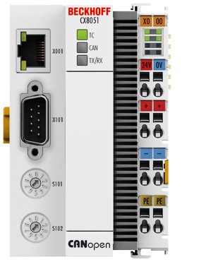
Ethernet interface X001
Interface X001 | Ethernet (CX805x) | Meaning |
|---|---|---|
LED green | on | Link present |
LED yellow | flashing | Activity |
CAN master LEDs of the CX8050
Labeling | Meaning | Color | Meaning |
|---|---|---|---|
TC | Indicates the status of the coupler | red | TwinCAT is in "stop" mode |
Green | TwinCAT is in "run" mode | ||
Blue (If red DIP switch 1 is set to on when starting the coupler) | TwinCAT is in "config" mode | ||
CAN | Shows the CAN status | Green on / Red off | CAN is OK |
Green off / Red on | CAN in bus off | ||
Green 200 ms / Red 200 ms | CAN Warning | ||
Green off / Red on | CAN not configured | ||
TX/RX | Indicates CAN errors | Green on / Red off | All nodes have NodeState = 0 |
Green 200 ms / Red 200 ms | All boxes in OP state, but the tasks have not yet started | ||
Green off / Red 200 ms | Not all nodes in OP | ||
Green off / Red on | No boxes configured |
CANopen slave LEDs of the CX8051
Labeling | Meaning | Color | Meaning |
|---|---|---|---|
TC | Indicates the status of the coupler | red | TwinCAT is in "stop" mode |
Green | TwinCAT is in "run" mode | ||
Blue (If red DIP switch 1 is set to on when starting the coupler) | TwinCAT is in "config" mode | ||
CAN | Shows the CAN status | Green on / Red off | CAN is OK |
Green off / Red on | CAN in bus off | ||
Green 200 ms / Red 200 ms | CAN Warning | ||
Green and red flashing rapidly | Baud rate search active | ||
Green off / Red on | CAN not configured | ||
TX/RX | Indicates CAN errors | Green on | Everything OK |
Green 200 ms / Red 200 ms | All boxes in OP state, but the tasks have not yet started | ||
Green off / Red 200 ms | Not all boxes in OP | ||
Green off / Red on | No boxes configured |
Power supply terminal LEDs
|
|
Operation with E-bus terminals | Operation with K-bus terminals |
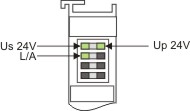
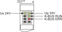
Display LED | Description | Meaning |
|---|---|---|
1 Us 24 V (top left, 1st row) | CX80xx supply voltage | connected to -24 V |
2 Up 24 V (top right, 1st row) | Power contacts supply voltage | connected to -24 V |
3 L/A (left centre, 2nd row) | EtherCAT LED | flashing green: EtherCAT communication active |
4 K-BUS RUN (right centre, 2nd row) | K-bus LED RUN | Lights up green: K-bus running, everything OK |
6 K-BUS ERR (bottom right, 3rd row) | K-bus LED ERR | Lights up red: K-bus error - see K-bus error code |
K-bus error codes
Error code | Error code argument | Description | Remedy |
|---|---|---|---|
Persistent, continuous flashing |
| EMC problems |
|
3 pulses | 0 | K-bus command error | - No Bus Terminal inserted |
4 pulses | 0 | K-Bus data error, break behind the Bus Coupler | Check whether the n+1 Bus Terminal is correctly connected; replace if necessary. |
n | Break behind Bus Terminal n | Check whether the Bus End Terminal 9010 is connected. | |
5 pulses | n | K-bus error in register communication with Bus Terminal n | Exchange the nth bus terminal |
6 pulses | 0 | Error at initialisation | Exchange Bus Coupler |
1 | Internal data error | Perform a hardware reset on the Bus Coupler (switch off and on again) | |
8 | Internal data error | Perform a hardware reset on the Bus Coupler (switch off and on again) | |
7 pulses | 0 | Process data lengths do not correspond to the configuration | Check the Bus Terminals for the configured Bus Terminals |
1..n | K-bus reset failed | Check the Bus Terminals |