CAN
CX8051
CANopen-Interface
The CANopen communication takes place via D-Sub port X101.
 | Debug via the Ethernet interface only The CX8051 does not support the ADS via CANopen. The program download and debugging can take place exclusively via the Ethernet interface. |
CANopen address
The CANopen address can be assigned via the rotary selector, or permanently in the System Manager. If the address is assigned permanently, the address switch is ignored.
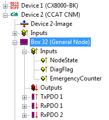
CANopen NodeState
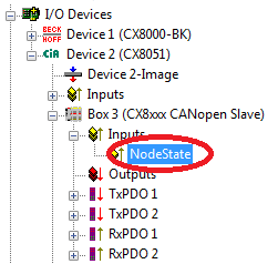
The NodeState can be used to display the state of the CANopen communication to find out whether the slave is engaged in data exchange (NodeState=0) or whether there is an error or problem.
0 = No error
128 = Node is Operational but not all RxPDOs were received
129 = Node is Pre-Operational
130 = Node is Stopped
CANopen process data
The CX8051 can exchange up to 16 PDOs (each with 8 bytes of process data) with the CANopen master in input and output direction via CANopen.
By default 2 PDOs are created in Tx and Rx direction. The PDOs can be filled with user data. The limit of 8 bytes per PDO must not be exceeded. Data are sent automatically when there is a change, unless the master is configured differently. At the planning stage please ensure that the data in a PDO "only" change at a moderate rate (e.g. not with ms frequency). Failure to adhere to this can lead to CAN overload. Particularly for low baud rates, the CAN can reach its limit quite quickly.
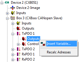
Creating data in the PDO
For each PDO you can create up 8 bytes of data. Variables of different type may be used, as long as the limit of 8 bytes is adhered to. For TxPDOs there is an additional control word, which can be used in cases where data are to be sent not only in the event of changes, but also when the data in the PDO have not changed. To change the control word it can simply be incremented, for example. If incrementation and data modification happen at the same time (i.e. in the same cycle), only one telegram is sent.
The RxPDOs had an additional status word, which is incremented on arrival of the PDO. This is useful in cases where data in the PDO are unchanged, since attention is drawn to the fact that new telegram with old data has arrived. This can be used for monitoring or to check whether a device still sends data on a regular basis.
Further PDOs can be added by clicking on the "CX8xxx CANopenSlave box". Please note that the COB ID is always zero from the 5th PDO, in which case it has to be entered manually.
CAN load
The CAN load should be taken into account during network planning and configuration: 500 kbit at 8 bytes of user data per frame results in a maximum number of 3707 frames per second. For reasons of network stability it is never advisable to run a CAN at 100% load. An upper bus load limit of 60% is recommended, which corresponds to 2221 frames per second. Example: A CX8051 with 8 Rx PDOs and 10 ms task time, resulting in 100 cycles per second for 8 PDOs. If PDO sending is event-driven, they are sent when the process data change. On the slave side this may be more frequent than every 10 ms. If the values only change once per 10 ms cycle, this results in 800 frames per second on the slave side and perhaps another 800 frames per second on the master side, plus heartbeat, sync telegrams and SDO communication. The example indicates that the upper limit of 2221 frames can be reached or indeed exceeded quite quickly in cases where rapid changes in input data lead to sending of PDOs with high frequency. This may be the case for analog inputs, for example, since their values usually change continuously. It is therefore advisable to control the send behavior by setting suitable parameter (inhibit time, filters) or to switch to cyclic sending.
|
Baud rate |
1 bytes data |
2 bytes data |
4 bytes data |
8 bytes data |
|---|---|---|---|---|
|
1 Mbaud |
15384 |
13333 |
10526 |
7407 |
|
500 kbaud |
7692 |
6666 |
5263 |
3703 |
|
100 kbaud |
1538 |
1333 |
1052 |
740 |
Table showing the number of theoretical CAN frames at 100% load for different CAN data sizes.
Virtual CANopen device interface
The virtual slave interface enables the creation of up to three virtual slaves on the same hardware interface. This enables the user to exchange more data with a CANopen master.
A maximum of 16 PDOs data can be configured for each slave, i.e. in total you can exchange 4 x 16 PDOs data in each direction.
Append a maximum of four CX8051 devices to your CAN device (fig. 1.0). Each of these devices is given a CAN address via the System Manager which can also be linked with the address selector (see Address switch). Add the process data PDOs under the box. For the CANopen master configure each of the four slaves like an independent device.
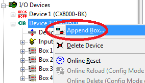 Fig.2: Creation of the 4 CANopen slave devices
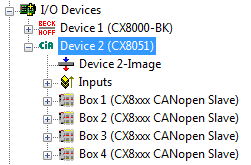 Fig.3: Appending the CAN modules
CX8050
CANopen interface / CAN interface
The CANopen communication takes place via D-Sub port X101. The CX8050 enables a CANopen master or "simple" CAN communication to be used.
CANopen address
The rotary selector (S101/102) of the CAN master has no purpose. The address selector can be read via the PLC (see address) and then be used for the applications.
CANopen NodeState
The NodeState (red) can be used to display the state of the CANopen communication to find out whether the slave is engaged in data exchange (NodeState=0) or whether there is an error or problem.
0 = No error
1 = Node deactivated
2 = Node not found
4 = SDO syntax error at StartUp
5 = SDO data mismatch at StartUp
8 = Node StartUp in progress
11 = FC510x Bus-OFF
12 = Pre-Operational
13 = Severe bus fault
14 = Guarding: toggle error
20 = TxPDO too short
22 = Expected TxPDO is missing
23 = Node is Operational but not all TxPDOs were received
The DiagFlag indicates whether an emergency telegram was received from the slave. The telegram can then be read in the System Manager or the PLC via ADS (see ADS interface). Please consult the slave manufacturer regarding interpretation of the data. The flag is reset once the Diag buffer was read.
The EmergencyCounter is incremented after each emergency telegram.
CAN Layer 2 communication
If you have selected this checkbox, the entire CANopen network management for this device is deactivated. It is not started, monitored etc. The PDO inputs are detected as pure CAN (layer 2) telegrams and enable the controller to operate in event driven mode.
CAN interface
Any CAN data can be sent via the CAN interface. There is a choice between 11-bit identifier (CAN 2.0A) or 29-bit identifier (CAN 2.0B).
Message structure with 29-bit support
- Length (0..8)
- CobId
- Bit 0-28: 11 Bit identifier / 29 Bit identifier
- Bit 30: RTR
- Bit 31: 0: normal Message (11 Bit Identifier), 1: extended Message (29 Bit-Identifier)
- Data[8]
Sending data: In NoOfTxMessages enter the number of data to be sent from the Tx buffer. If the buffer has capacity for 10 entries, the maximum number of telegrams that can be send consecutively is 10. "Length" defines the number of PDO data bytes (maximum 8 bytes). Enter the data, then enter the CAN message ID in "codId". Now increment the TxCounter value.
Sample code: Sending messages from the PLC
if Outputs.TxCounter = Inputs.TxCounter then
     for i=0 to NumberOfMessagesToSend do
          Outputs.TxMessage[i] = MessageToSend[i];
     End_for
     Outputs.NoOfTxMessages = NumberOfMessagesToSend;
     Outputs.TxCounter := Outputs.TxCounter + 1;
end_if
Sample code: Receiving messages from the PLC
if Outputs.RxCounter <> Inputs.RxCounter then
     for i := 0 to (Inputs.NoOfRxMessages-1) do
          MessageReceived[i] := Inputs.RxMessage [i];
     End_for
     Outputs.RxCounter := Outputs.RxCounter+1;
end_if