LED indicators
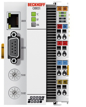
Ethernet interface X001
Interface X001 | Ethernet (CX8030, CX8031) | Meaning |
|---|---|---|
LED green | on | Link present |
LED yellow | flashing | Activity |
LED CX8030 Coupler
Labeling | Meaning | Color | Meaning |
|---|---|---|---|
TC | Indicates the status of the coupler | red | TwinCAT is in "stop" mode |
Green | TwinCAT is in "run" mode | ||
Blue (If red DIP switch 1 is set to on when starting the coupler) | TwinCAT is in "config" mode | ||
BF | Indicates the status of the PROFIBUS | Green on | PROFIBUS error-free |
Green flashing | PROFIBUS, at least one slave in error | ||
DIA | Indicates PROFIBUS errors | red illuminated | no PROFIBUS configured |
LED CX8031 and CX8030 Couplers configured as slave
Labeling | Meaning | Color | Meaning |
|---|---|---|---|
TC | Indicates the status of the coupler | red | TwinCAT is in "stop" mode |
Green | TwinCAT is in "run" mode | ||
Blue (If red DIP switch 1 is set to on when starting the coupler) | TwinCAT is in "config" mode | ||
BF | Indicates the status of the PROFIBUS | Green on | PROFIBUS in data exchange |
Green flashing | PROFIBUS is waiting for Cfg data | ||
DIA | Indicates PROFIBUS errors | - | - |
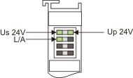
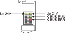
LED power supply terminal
|
|
Operation with K-bus terminals | Operation with E-bus terminals |
Display LED | Description | Meaning |
|---|---|---|
1 Us 24 V (top left, 1st row) | CX80xx supply voltage | connected to -24 V |
2 Up 24 V (top right, 1st row) | Power contacts supply voltage | connected to -24 V |
3 L/A (left center, 2nd row) | EtherCAT LED | flashing green: EtherCAT communication active |
4 K-BUS RUN (right center, 2nd row) | K-bus LED RUN | Lights up green: K-bus running, everything OK |
6 K-BUS ERR (bottom right, 3rd row) | K-bus LED ERR | Lights up red: K-bus error - see K-bus error code |
K-bus error code
Error code | Error code argument | Description | Remedy |
|---|---|---|---|
Persistent, continuous flashing |
| EMC problems |
|
3 pulses | 0 | K-bus command error |
|
4 pulses | 0 | K-Bus data error, break behind the Bus Coupler | Check whether the n+1 Bus Terminal is correctly connected; replace if necessary. |
n | Break behind Bus Terminal n | Check whether the bus end terminal 9010 is connected. | |
5 pulses | n | K-bus error in register communication with Bus Terminal n | Exchange the nth bus terminal |
6 pulses | 0 | Error at initialization | Exchange Bus Coupler |
1 | Internal data error | Perform a hardware reset on the Bus Coupler (switch off and on again) | |
8 | Internal data error | Perform a hardware reset on the Bus Coupler (switch off and on again) | |
7 pulses | 0 | Process data lengths do not correspond to the configuration | Check the Bus Terminals for the configured Bus Terminals |
1..n | K-bus reset failed | Check the Bus Terminals |