Cables, Plugs and Switches
The physics of the transmission
Physical aspects of the data transmission are defined in the PROFIBUS standard. See PROFIBUS layer 1 (physical layer).
The types of area where a fieldbus system can be used is largely determined by the choice of the transmission medium and the physical bus interface. In addition to the requirements for transmission security, the expense and work involved in acquiring and installing the bus cable is of crucial significance. The PROFIBUS standard therefore allows for a variety of implementations of the transmission technology while retaining a uniform bus protocol.
Cable-based transmission: This version, which accords with the American EIA RS-485 standard, was specified as a basic version for applications in production engineering, building management and drive technology. A twisted copper cable with one pair of conductors is used. Depending on the intended application area (EMC aspects should be considered) the screening may be omitted.
Two types of conductor are available, with differing maximum conductor lengths; see the „RS-485“ table. The pin assignment at the plug and the wiring are illustrated in the diagram. Note the special requirements on the data cable for baud rates greater than 1.5 Mbaud. The correct cable is a basic requirement for correct operation of the bus system. If a „simple“ 1.5 Mbaud cable is used, reflections and excessive attenuation can lead to some surprising phenomena. This could, for example be that some station is not connected, but when the neighboring station is unplugged the connection appears again. Or there may be transmission errors when a specific bit pattern is transmitted. The result of this can be that when the equipment is not operating, PROFIBUS works without faults, but that there are apparently random bus errors after start-up. Reducing the baud rate (< 93.75 kbaud) corrects this faulty behavior.
Cable-related malfunctions
If reducing the baud rate does not correct the error, then in many cases this can indicate a wiring fault. The two data lines maybe crossed over at one or more connectors, the termination resistors may not be switched on, or they may be active at the wrong locations.
 | Pre-assembled cables from Beckhoff Installation is made a great deal more straightforward if pre-assembled cables from Beckhoff are used. Wiring errors are avoided, and commissioning is more rapidly completed. The range includes fieldbus cables, power supply cables, sensor cables and accessories such as terminating resistors and T-pieces. Connectors and cables for field assembly are nevertheless also available. |
PROFIBUS Connection of the fieldbus box modules
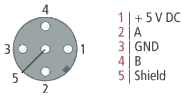
The M12 socket is inverse coded, and has five pins. Pin 1 is 5 V DC and 3 is GND for the active termination resistor. These must never be misused for other functions, as this can lead to destruction of the device. Pin 2 and pin 4 are the PROFIBUS signals. These must never be swapped over, as this will prevent communication. Pin 5 is the shield, and this is capacitatively coupled to the Fieldbus Box chassis.
PROFIBUS socket pin assignment
|
PROFIBUS conductors |
M12 |
D-Sub |
|---|---|---|
|
B red |
Pin 4 |
Pin 3 |
|
A green |
Pin 2 |
Pin 8 |
|
RS-485 transmission according to the PROFIBUS standard | |
|
Network topology |
Linear bus, active bus terminator at both ends, stubs are possible. |
|
Medium |
Screened twisted cable, screening may be omitted, depending upon the environmental conditions (EMC). |
|
Number of stations |
32 stations in each segment with no repeater. Can be extended to 127 stations with repeater |
|
Max. bus length without repeater |
100 m at 12 Mbit/s |
|
Max. bus length with repeater |
Line amplifiers, or repeaters, can increase the bus length to the order of 10 km. The number of repeaters possible is at least 3, and, depending on the manufacturer, may be up to 10 |
|
Transmission speed |
9.6, 19.2, 93.75, 187.5, 500, 1500 Kbit/s, up to 12 Mbit/s, adjustable in stages |
|
Plug connector |
9-pin D-Sub connector for IP20 |
Cabling for PROFIBUS DP and PROFIBUS FMS
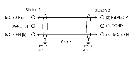
| Termination resistors at the conductor ends In systems with more than two stations all devices are wired in parallel. It is essential that the bus cables are terminated with resistors at the conductor ends in order to avoid reflections and associated transmission problems. |
Addressing
Setting of station addresses
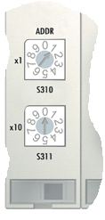
The PROFIBUS address must be set using the two rotary selection switches behind the transparent cover. The default setting is 11. Any address is permitted, but each address may only be used once within the network. The address is changed while the Fieldbus Box is switched off. To do this, unscrew the cover and use a screwdriver to move the switches to the desired position. Make sure that the switches engage properly. The change in address is active as soon as the device is switched on.
Address Fieldbus Box
The switch on the left represents the tens, while that on the right represents the units.
Address Bus Coupler
The switch S311 represents the tens, while that S310 represents the units.