EtherCAT
 | Incorrectly set address offsets for the EtherCAT slave interface lead to a crash. For devices with Arm® processors, pay attention to the alignment and set the correct address offset in TwinCAT.
|
Slave interface
The incoming EtherCAT signal is connected to the X101 interfaces. X102 goes to further EtherCAT Slave devices. The 10-pin DIP switch is intended exclusively for the “Hot Swap” (see Hot Swap). A maximum of 512 bytes of input and output data or 256 variables can be connected via the EtherCAT interface.
For example, creating 512 bytes individually will not work because it would require 512 variables.
Process data
How is process data created in TwinCAT?
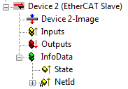
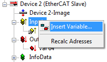
Once a CX8010 is scanned, the System Manager adds an “EtherCAT Slave” device. The interface has a very simple structure and usually consists only of “inputs”, “outputs” and InfoData. By clicking on the inputs, you can right-click to add data to the interface. The system then automatically addresses them.
|
|
The same is done with the outputs. Now link them to your PLC program or to the K-bus and/or E-bus terminals. If you only link from terminals to the EtherCAT process image, make sure that both devices possess a task that they trigger and that the task is also automatically started.
InfoData: The current AMSNet ID of the interface is stored here. You can evaluate the state in order to determine the state of the EtherCAT slave interface.
Process data with structures
To save many links, it is advisable to store data that you want to exchange in a data structure. Note, however, that an x86 system and an Arm® processor handle data structures with different variables in different ways. An Arm® processor always stores Word variables (2 bytes) at an even address and 4 DWORD variables (4 bytes) at an address that is divisible by 4.
Example
Data structure
byTest :BYTE;
udTest:UDINT;
Arm® address | Arm® variable | x86 address | Arm® variable |
Byte Offset 0 | Byte | Byte Offset 0 | BYTE |
Byte Offset 4 | UDINT | Byte Offset 1 | UDINT |
Sum: 8 bytes | Sum: 5 bytes | ||
You can determine the length of a data structure on both systems using the SIZEOF command. If there is a difference, this indicates that something is wrong with the data structure.
This problem can be solved by a smarter arrangement of variables or by working with filler or dummy variables.
Arm® address | Arm® variable | x86 address | Arm® variable |
Byte Offset 0 | Byte | Byte Offset 0 | BYTE |
Byte Offset 1 | BYTE (Dummy1) | ||
Byte Offset 2 | BYTE (Dummy2) | ||
Byte Offset 3 | BYTE (Dummy3) | ||
Byte Offset 4 | UDINT | Byte Offset 4 | UDINT |
Sum: 8 bytes | Sum: 8 bytes | ||
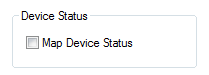
Device status
The device status indicates whether the EtherCAT slave interface is in OP mode and indicates the data communication via the toggle bit. The EtherCAT status can also be affected by the slave side in the output area.
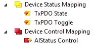
TxPDO State “1”: node is in OP mode; “0”: node is no longer in OP mode
TxPDO Toggle “1/0”: node is in data exchange
AIStatus Control
0x0000_0000 Normal mode (OP mode)
0x0001_0000 INIT mode
0x0002_0000 PREOP mode
0x0004_0000 SAFEOP mode
0x0008_0000 OP mode
All other bits are reserved!
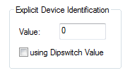
Hot Swap (Explicit Device Identification)
In applications where a CX8010 is to be replaced by another CX8010 during operation (with different applications on each CX8010), the individual CX8010 units can be distinguished from each other using Explicit Device Identification. These are sorted into a Hot Connect group.
The Explicit Device Identification Number can be set via the DIP switch or via software in System Manager. If it is to be used via the DIP switch, it must be enabled once in System Manager. When the system is started, the CX8010 will leave the switch on and operate with its setting.
ADS Interface AMS NetId
Reserved for extensions.
Advanced Settings
Reserved for extensions.
Distributed Clocks
Currently not supported.