PWM signal mode
Notice | |
Feedback at the 24 V outputs A voltage of 24 V at outputs 3 and 4 can destroy the device (feedback). No voltage may be applied to the outputs in PWM mode. |
The PWM signal mode enables a pulse width modulated binary signal to be output at outputs 3 and 4.
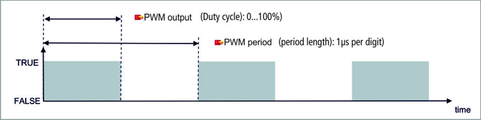
 Fig.22: Configurable inputs and outputs in PWM signal mode
This signal is separated into duty cycle (0... 100 %) and PWM clock frequency (15 Hz... 100 kHz). The LEDs are clocked with the outputs, and show the duty cycle by their brightness. The signal values are transferred in 16-bit values.
Technical data | Digital inputs |
|---|---|
Connection technology | PWM output |
Number of outputs | 2 |
Nominal voltage | 24 V DC (-15 %/+20 %) |
Load type | ohmic, inductive, lamp load |
Max. output current | 24 V/0.5 A (short-circuit proof) |
PWM clock frequency | 15 Hz…100 kHz |
Duty cycle | 0…100 % (TON > 20 ns, TOFF > 200 ns) |
Short circuit current | < 2 A typ. |
Special features | separate frequency can be set for each channel |
Connection cross-section | e*: 0.08…1.5 mm², |
Connection cross section AWG | e*: AWG 28…16, |
Strip length | 8 … 9 mm |
*e: single-wire, solid wire; f: stranded wire; a: with ferrule