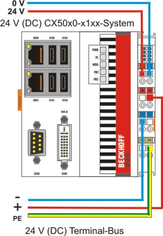
Power supply
This power supply unit is equipped with an I/O interface, which permits connection of the Beckhoff Bus Terminals. The power is supplied via the upper spring-loaded terminals labeled “24V” and “0V”.
The supply voltage supplies the CX system ant the terminal Bus and Bus Terminal with a voltage of 24 V DC (-15 %/+20 %). The dielectric strength of the power supply unit is 500 Vrms. Since the Terminal Bus (K- and E-bus) only transfers data, a separate power supply is required for the Bus Terminals. This is provided by means of the power contacts, which are not connected to the power supply.
Requirements for the 24V power supply
The power supply must be capable to supply 4A to guarantee proper function of CPU module and terminals.
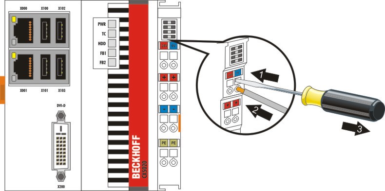
The terminals are implemented in spring force technology. Connect the cables as follows:
- Open a spring-loaded terminal by slightly pushing with a screwdriver or a rod into the square opening above the terminal.
- The wire can now be inserted into the round terminal opening without any force.
- The terminal closes automatically when the pressure is released, holding the wire securely and permanently.
|
Wire size width |
0.5 ... 2.5 mm2 |
AWG 20 .. AWG 14 |
|
Wire stripping length |
8 ... 9 mm |
0.33 inch |
LED
If the power supply unit is connected correctly and the power supply is switched on, the two upper LEDs in the terminal prism are green. The left LED (Us) indicates the CPU supply. The right LED (Up) indicates the terminal supply. The other LEDs indicate the Terminal Bus status. A detailed description of the LEDs can be found in section "LED troubleshooting".
UL requirements
| |
Compliance of the UL requirements For the compliance of the UL requirements the CX-Controllers should only be supplied by a 24 VDC supply voltage, supplied by an isolating source and protected by means of a fuse (in accordance with UL248), rated maximum 4 Amp.by a 24 VDC power source, that has to satisfy NEC class 2. A NEC class 2 power supply shall not be connected in series or parallel with another (class 2) power source!This UL requirements are valid for all supply voltages of the CX-Controllers! |

| |
Compliance of the UL requirements To meet the UL requirements, the CX-Controllers must not be connected to unlimited power sources! |

Power contact PE
Notice | |
Powerkontakt "PE" The “PE” power contact must not be used for other potentials. "PE" und "0V" (24V CX-System supply) have to be on the same potential. (connected in the cabinet) The wiring the cabinet has to follow the Norm EN EN 60204-1:2006: Safety of machinery - Electrical equipment of machines - (PELV = Protective Extra Low Voltage) EN 60204-1:2006 chapter 6.4.1:b): One side of the circuit or a point of the energy source of the circuit must be connected to protective earth system |
Notice | |
Interrupt power supply / switching off If the power supply should be disconnected the "0V" must not be disconnected. Always disconnect the “24V” wire first. Otherwise there can be electrical current flow via the shield. Possibly connected devices with own power supply (e.g. panel) must have the same electrical potential for "PE" and "GND" as the CX-unit. Otherwise the CX-unit and/or the connected device can be damaged. |