CX2500-0030 connections
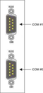
The CX2500-0030 system interface provides two RS232 interfaces. The interfaces are arranged on a 9-pole Sub-D pin contact strip. Up to 4 interfaces can be attached. This means that up to 9 serial interfaces (four CX2500-0030 modules and the optional CX20x0-N030 interface) can be connected to the CX20x0 system. The system shows the optional CX20x0-N030 interface as COM1. The pin assignment of all connectors is identical and is shown below at the side.
The maximum baud rate on both channels is 128 kbit. The interface parameters are set via the operating system or from the PLC program.
RS232 COM interface (connector) /( X300, X301
|
PIN |
Signal |
Type |
Description |
|---|---|---|---|
|
1 |
DCD |
Signal in |
Data Carrier Detected |
|
2 |
RxD |
Signal in |
Receive Data |
|
3 |
TxD |
Signal out |
Transmit Data |
|
4 |
DTR |
Signal out |
Data Terminal Ready |
|
5 |
GND |
Ground |
Ground |
|
6 |
DSR |
Signal in |
Dataset Ready |
|
7 |
RTS |
Signal out |
Request to Send |
|
8 |
CTS |
Signal in |
Clear to Send |
|
9 |
RI |
Signal in |
Ring Indicator |
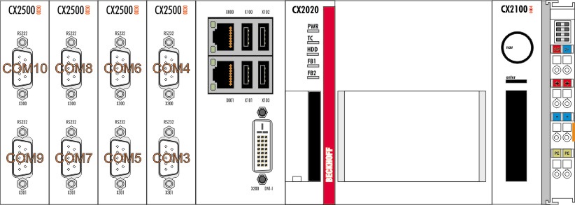
In the operating system the interfaces are numbered from right to left (starting from the CPU) and from top to bottom (i.e. X301 -> COM n and X300 -> COM n+1 for n ={ 3, 5, 7, 9}):
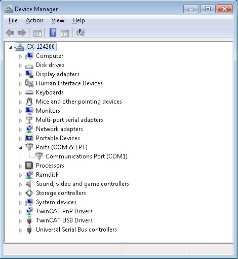
If the interfaces configuration is changed, the numbering of the interfaces changes. To obtain unique interface numbering, we recommend to delete the interfaces manually from the Device Manager.
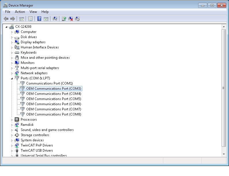
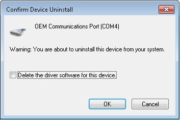
To do this, select Uninstall from the context menu.
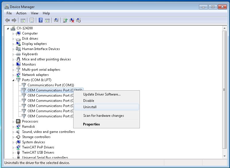
In the following dialog the driver must remain in the system. The box must not be ticked.
Once all serial interfaces, apart from COM1, have been removed in the Device Manager, the system can be shut down and de-energized.
The hardware configuration can now be changed. Once the configuration has been changed as required, the system can be restarted. The operating system restarts and numbers the interfaces as described above.