Displaying texts
Software connection for the display
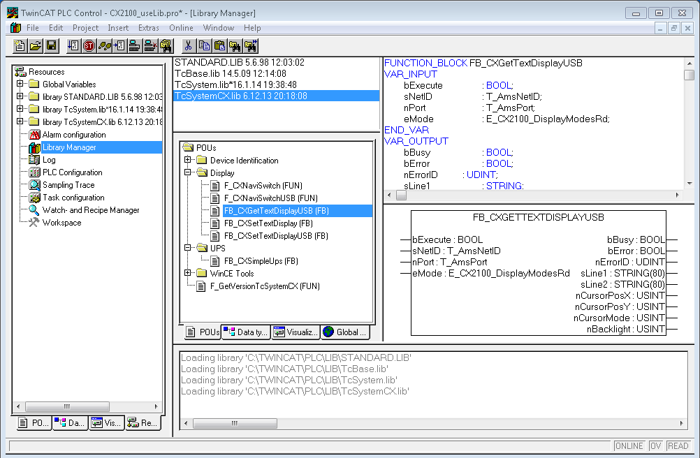
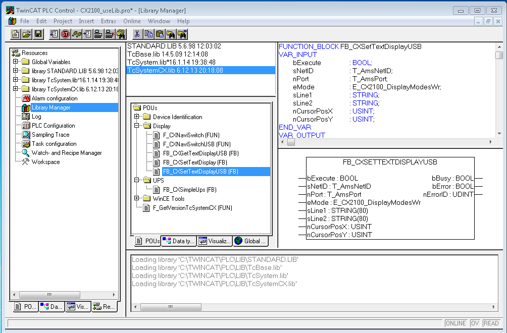
There is a possibility to set static texts via the System Manager. Alternatively there are two TwinCAT function blocks. Their names are FB_CXSetTextDisplayUSB(FB) and FB_CXGetTextDisplayUSB(FB). Parameters are written with FB_CXSetTextDisplayUSB(FB) and the status values are read from the function block with FB_CXGetTextDisplayUSB(FB). A detailed documentation of the function blocks can be found in the TwinCAT software documentation. The two screenshots show the associated libraries for the function blocks.
 | Availability of the function blocks These function blocks are available in the TwinCAT builds starting from version TC2.11 R3 Build 2240 With older versions an update is required for the use of the function blocks. |
Illustration of the display with the System Manager
There are six tabs in the System Manager. These are briefly described below. The focus is thereby placed on the parameter that is relevant for the power supply unit
Tab: General
The general properties of the power supply unit are displayed here.
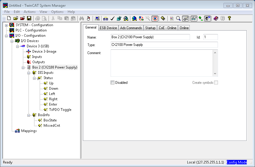
Name | Name of the EtherCAT device |
Id | Number of the EtherCAT device |
Type | EtherCAT device type |
Comment | Here you can add a comment (e.g. regarding the system). |
Disabled | Here you can deactivate the EtherCAT device. |
Tab: ESB Device
The settings for the exchange of data between the power supply unit and the system are made and/or displayed here.
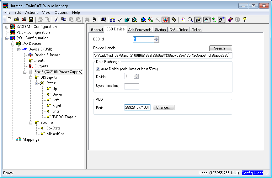
ESB Id | Serial numbers of the devices on the BUS |
Device Handle | Pointer to the device driver |
Data Exchange | Cycle in which the communication takes place |
ADS | Port address for ADS access |
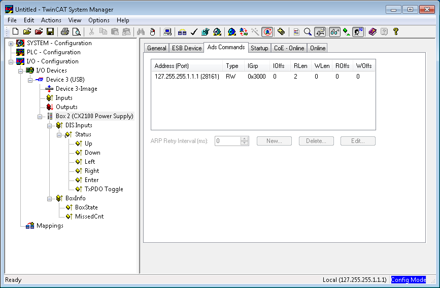
Tab: ADS Commands
The range for ADS communication is displayed here.
Tab: CoE Online
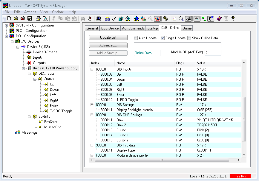
CoE interface – parameter management in the EtherCAT system
Many different devices are used in an automation environment. These devices can be used separately or together in a group on a bus system. Such devices can be controllers, shaft encoders, servo drives, motors, I/O modules or sensors among other things. Depending upon complexity, such a device must be parameterizable/adjustable for the respective requirement. Parameterization is perhaps not necessary in the case of a simple digital 24 V input with a fixed switching threshold and delay; in the case of a shaft encoder, however, it will not be possible to do without it (e.g. number of lines, absolute or relative, data format, etc.) On top of that it can be of interest to store data in the device during production or operation. The manufacturer could store production data such as device name, serial number, firmware version, calibration data or date of manufacture, if necessary provided with protection against access or amendment. The user could store user calibration data and the application-specific settings in the device.
In order to create a user-friendly interface for device operation, different organizations have created various standards in which the following are defined: the available device classes (e.g.: ‘rotary encoder’, ‘analog input module’ class), the parameters that each representative of such a class has (obligatory and optional elements), the locations where these parameters can be found and the mechanism with which they are to be changed. EtherCAT follows the so called CoE standard here: Can-Application-protocol-over-EtherCAT.
Can-over-EtherCAT
The CiA organization (CAN in Automation) pursues among other things the goal of creating order and exchangeability between devices of the same type by the standardization of device descriptions. For this purpose so-called profiles are defined, which conclusively describe the changeable and unchangeable parameters of a device. Such a parameter encompasses at least the following characteristics:
- Index number – for the unambiguous identification of all parameters. The index number is divided into a main index and a subindex in order to mark and arrange associated parameters.
- Main index
- Subindex, (offset by a colon “:”) - Official name – in the form of an understandable, self-descriptive text
- Specification of changeability, e.g. whether it can only be read or can also be written
- A value – depending upon the parameter the value can be a text, a number or another parameter index.
Example: the parameter ‘Vendor ID’ might have the index number 4120:01 and the numerical value ‘2’ as the ID of a Beckhoff device.
Since hexadecimal values are favored in the machine environment, the parameter is represented from the user’s point of view as if it had the RO property (read only), because the vendor ID should not be changed by the user.
Such a list of parameters, the whole of the device-specific CoE directory, can become very extensive. The first entries of a Beckhoff EL3152 analog input terminal appear as follows in the TwinCAT System Manager:
The index numbers are specified in the profile; they begin in EtherCAT with x1000, because the underlying entries do not have to be displayed.
CoE directory – availability
An EtherCAT device can have a CoE directory, but does not need to have one. Simple slaves need no parameter directory or do not have the controller required for administration. On the other hand, the EtherCAT master (like TwinCAT) as a software EtherCAT device can also manage a CoE directory.
If present, the CoE directory is in operation from the PREOP state.
The object directory can be read via the SDO information service (Service Data Objects).
CoE directory – localization in the EtherCAT Slave
The CoE directory as a parameter system must be administrated in the device in the firmware (FW) in the local controller. This is the so-called online directory, because it is only available to the user if the EtherCAT slave is in operation with operating voltage supplied and, if applicable, can be manipulated via EtherCAT communication.
So that the parameters can be viewed and changed in advance without the presence of a slave, a default copy of the entire directory is usually stored in the device description file ESI (XML). This is called the offline directory. Changes in this directory do not affect the later operation of the slave with TwinCAT. The xml files can be obtained from the Beckhoff website in the Download area.
The TwinCAT system manager 2.11 can display both lists and marks this:
in the online directory | in the offline directory |
the actual current slave list is read. This may take several seconds, depending on the size and cycle time | the offline list from the ESI file is displayed. In this case modifications are not meaningful or possible. |
the actual identity is displayed | the configured status is shown under Identity |
the firmware and hardware version of the equipment according to the electronic information is displayed | no firmware or hardware version is displayed, since these are features of the physical device |
a green online is visible in the TwinCAT System Manager, CoE Online tab | a red offline is visible in the TwinCAT System Manager, CoE Online tab |
Classification
Different CoE parameter types are possible, including string (text), integer numbers, Boolean values or larger byte fields. They can be used to describe a wide range of features. Examples of such parameters include manufacturer ID, serial number, process data settings, device name, calibration values for analog measurement or passwords.
The ranges in the Slave CoE that are important for the application-oriented EtherCAT fieldbus user are
- x1000: This is where fixed identity information for the device is stored, including name, manufacturer, serial number etc., plus information about the current and available process data configurations.
- x8000: This is where the operational and functional parameters for all channels are stored, such as filter settings or output frequency.
The following ranges are also of interest
- x4000: In some EtherCAT devices the channel parameters are stored here (as an alternative to the x8000 range).
- x6000: Input PDOs ("input" from the perspective of the EtherCAT master)
- x7000: Output PDOs ("output" from the perspective of the EtherCAT master)
Channel-based order
The CoE directory is located in EtherCAT devices that usually encompass several functionally equivalent channels. e.g. a 4-channel 0 – 10 V analog input terminal also has 4 logical channels and thus 4 identical sets of parameter data for the channels. In order to avoid having to list each channel in the documentation, the placeholder "n" tends to be used for the individual channel numbers.
In the CoE system 16 indices, each with 255 subindices, are generally sufficient for representing all channel parameters. The channel-based order is therefore arranged in 16dec/10hex steps. The parameter range x8000 exemplifies this:
Channel 0: parameter range x8000:00 ... x800F:255
Channel 1: parameter range x8010:00 ... x801F:255
Channel 2: parameter range x8020:00 ... x802F:255
tbc...
This is generally written as x80n0.
CoE directory – changes of value
Several parameters, in particular the setting parameters of the slave, are variable and can be written by the user from the fieldbus side. This can be done in write or read mode
via the System Manager (fig. 3) by the operator clicking on it
The values are then changed directly in the online-connected slave.
This is useful for commissioning of the system/slaves. Click on the row of the index to be parameterized and enter a value in the "SetValue" dialog.
from the controller/PLC via ADS e.g. by the function blocks from the TcEtherCAT.lib library
This is recommended for modifications when the system is running or if no System Manager or operating staff are available.
during the EtherCAT startup through predefined commands, the so-called startup list.
The TwinCAT configuration is usually created in advance without EtherCAT slaves actually being present. Then it should be possible before commissioning to adjust known properties such as filter settings offline in order to accelerate commissioning.
CoE directory – startup list
| Start-up list Changes made to the local CoE directory of the EtherCAT slaves are lost with the old device in case of exchange. If a device is replaced with a new Beckhoff device, it will have the default settings. It is therefore advisable to link all changes in the CoE list of an EtherCAT slave with the Startup list of the slave, which is processed whenever the EtherCAT fieldbus is started. In this way a replacement EtherCAT slave can automatically be parameterized with the specifications of the user. |
The startup list is used for these cases: the values here, which are entered by the user, are transmitted to the respective slave upon each EtherCAT state transition/start. A startup entry consists of
- Time: the state transition in which the command is sent
PS (PREOP-->SAFEOP) is usually the correct choice, since an EtherCAT slave then switches to operative input mode. - Index:Subindex
- Data
The order of the entries is not taken into account: all entries to which a state transition applies are handed over simultaneously as asynchronous commands to the EtherCAT system and executed there, as soon as the bus load allows. No check is made of whether an identical entry is already present in the slave. The corresponding values are adopted upon clicking the entry 8000:01; 01 is entered in Data as the desired value. The entry ‘P->S’ marks the time of the execution.
CoE directory – data management
| Data management If slave CoE parameters are modified online, Beckhoff devices store any changes in a fail-safe manner in the EEPROM, i.e. the modified CoE parameters are still available after a restart. The situation may be different with other manufacturers. If EtherCAT slaves are used which are unable to store local CoE values permanently, the Startup list must be used. |
Summary of the characteristics
Not every EtherCAT device must have a CoE directory
If a CoE directory is present, it is administrated, prepared for querying and writing and stored in the device by the controller.
The EtherCAT master can be used for viewing/querying/changing, or a local user interface on the device (keypad, screen) allows access.
Changed settings are stored fail-safe in Beckhoff devices.
If the device is later exchanged, however, the settings that have been changed from the series standard are lost. The EtherCAT master can then load the changed CoE parameters into the new device at startup, if it is set up appropriately.
So that a CoE directory is available offline during the preparation for configuration, it can be contained in the device description as a copy.
The extent to which the CoE directory is supported depends on the capabilities of the EtherCAT master.
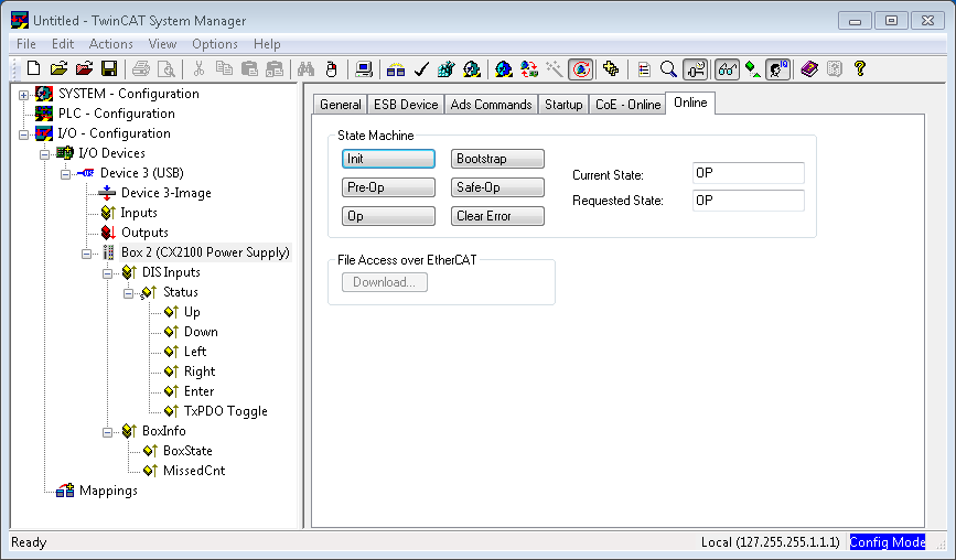
Tab: Online
the state machine of the EtherCAT communication is displayed here. It can also be switched to a different state here. This is done by selecting the desired state by a mouse-click on the appropriate button. The individual states are briefly described below. For further information, please refer to the EtherCAT system description on our webpage.
EtherCAT State Machine
The state of the EtherCAT slave is controlled via the EtherCAT State Machine (ESM). Depending upon the state, different functions are accessible or executable in the EtherCAT slave. Specific commands must be sent by the EtherCAT master to the device in each state, particularly during the bootup of the slave.
A distinction is made between the following states:
- Init
- Pre-Operational
- Safe-Operational and
- Operational
- Boot
The regular state of each EtherCAT slave after bootup is the OP state.
Init
After switch-on the EtherCAT slave in the Init state. No mailbox or process data communication is possible. The EtherCAT master initializes sync manager channels 0 and 1 for mailbox communication.
Pre-Operational (Pre-Op)
During the transition from Init to Pre-Op, the EtherCAT slave checks whether the mailbox has been correctly initialized. Mailbox communication is possible in the Pre-Op state, but no process data communication. The EtherCAT master initializes the sync manager channels for process data (from sync manager channel 2), the FMMU channels and, if the slave supports configurable mapping, PDO mapping or the sync manager PDO assignment. In this state the settings for the process data transfer and perhaps terminal-specific parameters that may differ from the default settings are also transferred.
Safe-Operational (Safe-Op)
During transition between Pre-Op and Safe-Op the EtherCAT slave checks whether the sync manager channels for process data communication and, if required, the distributed clocks settings are correct. Before it acknowledges the change of state, the EtherCAT slave copies current input data into the associated DP-RAM areas of the EtherCAT slave controller (ECSC).
Mailbox and process data communication are possible in the Safe-OP state; however, the slave maintains its outputs in the safe state and does not output them. The input data, however, are already cyclically updated.
Operational (Op)
Before the EtherCAT master switches the EtherCAT Slave from Safe-Op to Op, it must transmit already valid output data. In the Op state the slave copies the output data of the master to its outputs. Process data and mailbox communication is possible.
Boot
In the Boot state the slave firmware can be updated. The Boot state can only be reached via the Init state. In the Boot state mailbox communication is possible via the File-Access over EtherCAT (FoE) protocol, but no other mailbox communication and no process data communication is possible.