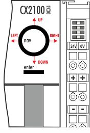
Operating principle of the button
The CX2100-0xx4 power supply units all have four navigation switches and an Enter button. The buttons can therefore be used to enter five basic states
Button | Value | Button | Value |
UP | 4 | RIGHT | 32 |
DOWN | 8 | ENTER / SELECT | 64 |
LEFT | 16 |
|
|
Combined inputs, such as UP + RIGHT or UP + RIGHT + ENTER can also be entered. Each value is made available separately as a boolean value and can be linked in the PLC.
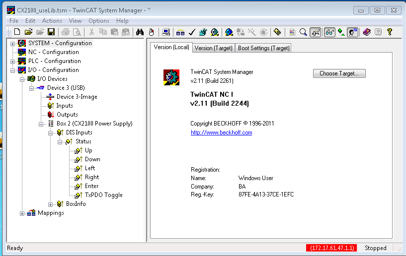
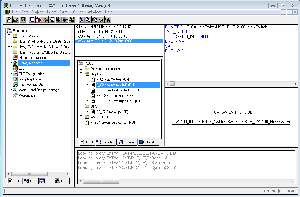
The values of the button can be assessed as a numerical value via a TwinCAT function. A combination of the buttons can also be assessed via the value. The register can be accessed from within a PLC program, and the value can be assessed. This requires a variable of type USINT to be created first in the PLC program. This is then called as a parameter in the ‘F_CXNaviSwitchUSB’ function. The code fragment shows the declaration of the required variables.
PROGRAM MAIN
VAR
    bUp AT %I*        : BOOL;
    bDown AT %I*    : BOOL;
    bLeft AT %I*    : BOOL;
    bRight AT %I*    : BOOL;
    bEnter AT %I*    : BOOL;
    bToggle AT %I*    : BOOL;
    Taster        : USINT; (* als Summenwert *)
    eNaviSwitchCx2 : E_CX2100_NaviSwitch;
END_VAR
(* get navi switch *)
eNaviSwitchCx2 := F_CXNaviSwitchUSB(Taster);
The push button can be accessed from the PLC program through the Taster variable. Then, a simple CASE statement can be used to evaluate the switch and initiate the desired function. For example:
CASE Taster OF
    4 : ACTION  := UP;
    8 : ACTION  := DOWN;
    16: ACTION  := LEFT;
    32: ACTION  := RIGHT;
    64: ACTION  := SELECT;
END_CASE;
In this case, "ACTION" is a newly defined ENUM type. It is also possible for the desired action to be activated immediately.
The sum of the numerical values is used for the combined functions. In other words, UP (4) and RIGHT (32) would be 4 + 32 = 36 (top right). The values are: {UP (4), DOWN(8), LEFT(16), RIGHT(32) and ENTER(64)}. In this way only useful combinations are possible.