Structure
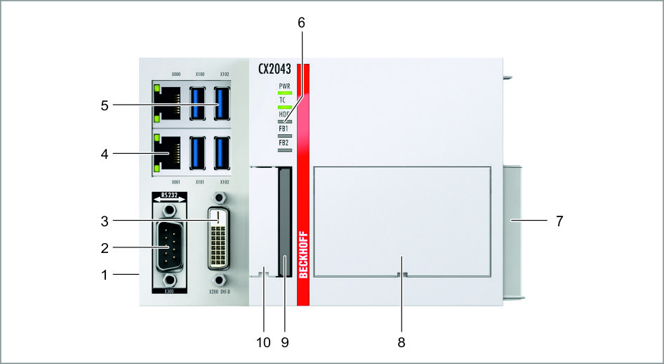 Fig.1: Example: Embedded PCs CX2043 with active cooling.
No. | Component | Description |
|---|---|---|
1 | Multi-pin connection (left) | Extension through system modules and fieldbus modules of type CX2500. |
2 | Optional interface (X300). | Space for interfaces such as RS232, EtherCAT, CANopen or others. The optional interface must be ordered ex factory and cannot be retrofitted retrospectively. |
3 | Interface for a monitor or Panel. | |
4 | RJ45 Ethernet interfaces (X000, X001). | For connecting to local networks, internet or EtherCAT. |
5 | USB interfaces (X100, X101, X102, X103). | Interfaces for peripheral devices such as mouse, keyboard or USB memory. |
6 | Diagnostic LEDs for power supply, TwinCAT, CFast card and optional interface. | |
7 | Multi-pin connection (right) | Connection for extension modules of type CX2550 and for power supply units of type CX2100. |
8 | Fan cartridge (under the front flap). | The fan cartridge is provided as standard for the CX2043. The CX2033 can be ordered ex factory with active cooling. |
9 | CFast card slot. | Slot for industrial CFast cards. |
10 | Battery compartment (under the front flap). | Power supply for the battery-backed clock for time and date. |