Controlling theUPS from the PLC
It is possible to control the UPS module from the PLC. There are two TwinCAT blocks that permit this control. This allows the PLC program to deal with a power failure. It is, however, first necessary to make some settings in the TwinCAT System Manager, so that the UPS can be properly included. The UPS module is integrated in the TwinCAT System Manager, as described under Commissioning. It is necessary, however, for a few important settings to be made so that the PLC can obtain control. The controller must be switched off in the System Manager. It is also necessary for the hardware inputs and outputs of the UPS to be linked to the corresponding variables in the PLC program. The inputs and outputs must be declared in the program as GLOBAL variables. (Further details are given below.) First the settings of the System Manager are described.
NecessarySystem Manager settings:
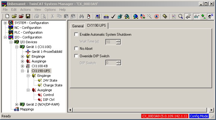
-Everything must be set to OFF! In other words, on the CX1190 UPS tab, neither "Enable Automatic Shutdown" nor "No Abort" may be activated.
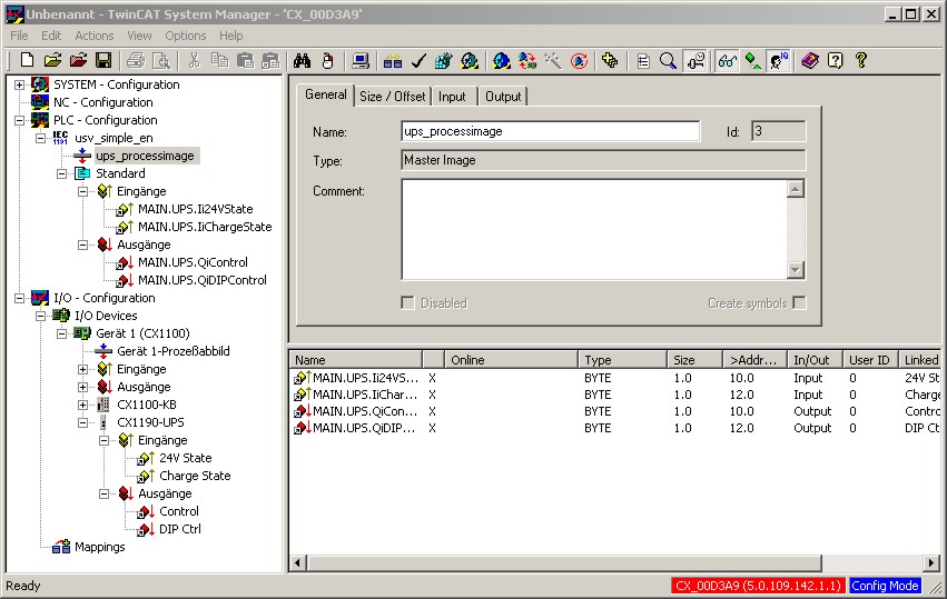
-In addition, both inputs (24V State and Charge State) and both outputs (Control and DIP Control) of the System Manager must be linked in the PLC to the UPS block in the corresponding variables.
The illustration shows the UPS being incorporated in the System Manager. The inputs and outputs of the UPS will be found both in the process image and in the hardware image in the hierarchy browser.
The signals are associated by a double-click. This association is required in order for the function block in the PLC program to operate properly. The PLC process image will, however, not be available until after the program has been compiled. This means that it must be linked into a PLC program before being linked with the UPS control block.
Details of linking signals are given in the documentation for the TwinCAT System Manager.
Linking the UPS control block into a PLC program:
The UPS is controlled from the PLC, with the aid of the FB_CX1000SimpleUps function block which is in the TC CX1000System.lib. This must, however, be linked by the library administrator. If this has been done, the block is available as a function block. It is instanced as such in the declarations part of the program.
PROGRAM MAIN_UPS
VAR
    UPS : FB_CX1000SimpleUps;
END_VAR
It is then called from the program with its parameters. There are three parameters for this function block:
- bDIPDisable : BOOL;
- iDischargeLevel : USINT;
- tDelay : TIME;
"tDelay" sets the maximum retention time for which the power may be absent before the UPS switches the PLC off. The permitted entries here are between 0 and 10 seconds. The boolean expression "bDIPDisable" allows the setting of the rotary switch on the UPS to be ignored. If the value is "TRUE" then the value set by "iDischargeLevel" is used as the valid retention time. The call then looks like this:
UPS(
    bDIPDisable := TRUE, (* TRUE for DIP switch override *)
    iDischargeLevel := 30, (* Values from 0.1, ... 9 *)
    tDelay := t#5s     (* Retention time before shutdown t#0s .. t#10s *)
);
In order for the function block to operate, the signals that are to be linked in TwinCAT's System Manager must be created as variables. This is done automatically when the process image is read into the System Manager. The linking process stores the addresses in the "TwinCAT_Configuration" file, and they are introduced during the next call to the compiler. (A more precise description can be read in the description of TwinCAT.) Alternatively it is possible to assign the addresses by hand. After compilation, warnings about the missing configuration for the signals are displayed. The signals are inserted into the "Variablen_Konfiguration" file through the "Insert -> All instances" menu item. It is possible to enter the addresses for the signals here. (E.g. MAIN.UPS.Li24VState AT %IB0 : BYTE for memory address 0).
VAR
    MAIN.UPS.Ii24VState AT %IB0 : BYTE;
    MAIN.UPS.IiChargeState AT %IB1 : BYTE;
    MAIN.UPS.QiControl AT %QB0     : BYTE;
    MAIN.UPS.QiDipControl AT %QB1 : BYTE;
END_VAR
The block supplies a few status signals for evaluating the program environment. These can then be used for control, e.g. saving the process data in NOVRAM, or for setting defined states or positions for axes. In detail, the block supplies the following signals:
- bPowerFailure : BOOL;
- bShutdownActive : BOOL;
- bUpsReady : BOOL;
- b24VInOK : BOOL;
- bHolding : BOOL;
- tTimeUntilShutdown : TIME;
- eUpsState : E_UPS_STATE
"bPowerFailure" returns "TRUE" when a failure in the power supply voltage is detected . The signal goes back to "FALSE" when the input voltage returns.
"bShutdownActive" indicates that a stop or shutdown is being executed.
"bUpsReady" indicates that the UPS is providing the output voltage.
"b24VInOK" reports that the UPS is being supplied with 24 V input voltage.
"bHolding" returns "TRUE" when a failure in the supply voltage has been detected, and the retention time has not yet elapsed.
"tTimeUntilShutdown" indicates the retention time remaining until shutdown.
"eUpsState" displays the status of the UPS [UNDEF | CHARGING | CHARGED | DISCHARGE | DISCHARGE_RESTART | OUTPUT_OFF | OVERLOAD
NOTICE | ||
The function block bridges short supply voltage drop-outs without generating a shutdown, while longer supply failures cause TwinCAT to be stopped and the operating system to be shut down.The CX10x0 is switched off by the UPS when it has reached it is discharge limit, even if the current returns during the shutdown.The CX10x0 is switched on again by the UPS once the UPS is fully charged. | ||
If it is necessary for the UPS to behave in a different way, e.g. with a longer retention time, resetting the bus, or definitely restarting the PLC even when the power failure was short, then the FB_CX1000UPSHANDLING function block from TC CX1000System.lib can be used as an alternative. This library must, however, be integrated through the library administrator. If this has been done, the block is available as a function block. It is instanced as such in the declarations part of the program.
PROGRAM MAIN_UPS
VAR
    UPS : FB_CX1000UPSHANDLING;
END_VAR
It is then called from the program with its parameters. There are seven parameters for this function block:
- bAutoReset : BOOL;
- bDIPDisable : BOOL;
- bShutdown24V : BOOL;
- bShutdown5V : BOOL;
- iDischargeLevel : USINT;
- bTcStopOnly : BOOL;
- tDelay : TIME;
"bAutoReset" does not switch the CX10x0 system off if the supply voltage returns in time (this is set under "tDelay"). If this behaviour is wanted, the input must be set to "TRUE". As in the case of the other module, "bDIPDisable" can be used to ignore the setting of the rotary switch (by setting the input to "TRUE"). In that case again, the value set under "iDischargeLevel" is used. "bShutdown24V" switches off the 24V voltage. Warning! "bShutdown5V" is not used at present. This input must always be set to "FALSE"! It is, however, only necessary to ignore it, as it is initialised with "FALSE". "iDischargeLevel" indicates the discharge capacity of the UPS. The range of values extends from 0 to 9, whereby, for instance, 3 corresponds to switch setting 3 and means that the UPS will switch off after losing 30% of its capacity. "TDelay" indicates the retention time before a stop or shutdown is initiated. The "bTcStopOnly" switch is required for writing the persistent data under the "Microsoft Windows CE" operating system. Shutdown causes the system to reboot. It is necessary, however, to stop TwinCAT in order to write the persistent data. This stop signal is set through the "bTCStopOnly" input ("bTcStopOnly" := "TRUE"). Under "Microsoft Windows XP embedded" shutting down causes the persistent data to be written. The switch is therefore not necessary (bTcStopOnly = FALSE).
The call then looks like this:
UPS(
    bAutoReset := TRUE; (* TRUE if operation is to continue when the supply returns)
    bDIPDisable := TRUE;    (* TRUE for DIP switch override *)
    bShutdown24V := FALSE;(* Only TRUE if switching off is desired -> everything OFF !!! *)
    bShutdown5V := FALSE;(* DO NOT USE ---> reserved function *)
    iDischargeLevel := 3; (* Values from 0.1, ... 9 *)
    bTcStopOnly := TRUE;    (* Under WINDOWS CE in order to save the persistent data, otherwise FALSE*)
    tDelay     := t#5s; (* Retention time before shutting down *)
);
This function block also needs further variables for its operation. They are linked in TwinCAT's System Manager with signals from the UPS. These variables still have to be created. This is done automatically when the process image is read into the System Manager. The linking process stores the addresses in the "TwinCAT_Configuration" file, and they are introduced during the next call to the compiler. (A more precise description can be referred to in the description of TwinCAT.) Alternatively it is possible to assign the addresses by hand. After compilation, warnings about the missing configuration for the signals are displayed. The signals are inserted into the "Variablen_Konfiguration" file through the "Insert -> All instances" menu item. It is possible to enter the addresses for the signals here. (E.g. MAIN.UPS.Li24VState AT %IB0 : BYTE for memory address 0).
VAR
    MAIN.UPS.Ii24VState AT %IB0 : BYTE;
    MAIN.US.IiChargeState AT %IB1 : USINT;
    MAIN.UPS.QiControl AT %QB0     : BYTE;
    MAIN.UPS.QiDipControl AT %QB1 : USINT;
    MAIN.UPS.IbPowerFault AT %I : BOOL;

END_VAR
The block supplies a few status signals for evaluating the program environment. These can then be used for control, e.g. saving the process data in NOVRAM, or for setting defined states or positions for axes. In detail, the block supplies the following signals:
- bPowerFailure : BOOL;
- bShutdownActive : BOOL;
- bUpsReady : BOOL;
- b24VInOK : BOOL;
"bPowerFailure" returns "TRUE" when a failure in the power supply voltage is detected . The signal goes back to "FALSE" when the input voltage returns.
"bShutdownActive" indicates that a stop or shutdown is being executed.
"bUpsReady" indicates that the UPS is providing the output voltage.
"b24VInOK" reports that the UPS is being supplied with 24 V input voltage.
NOTICE | ||
The function block gives the PLC program full control over the behaviour of the UPS. Depending on the operating mode, the developer must see to it that the system is in the desired state when switched off, and/or that the system behaves correctly when it restarts. Problems that can occur include, for instance:The system has halted, the UPS however provides voltage again -> the system remains inert, even though a power supply is present.The system starts again, but the UPS is still in the discharge phase, and does not switch off until fully discharged -> the system starts up, but then is powered down without warning. | ||