Discharging time
The measure the time for discharging of the different UPS modules a precision load was connected to the UPS. The retention time was measured depending of load and switch setting. The test scene is shown in the picture below.
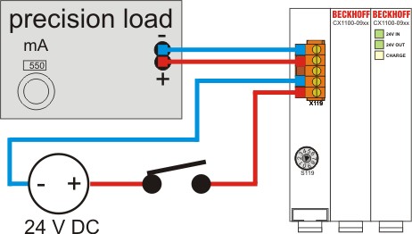
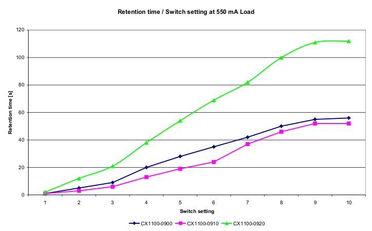
A measurement starts app. 30 seconds after the module signals full charge (CHARGE glows green). The power supply to the UPS is disconnected by releasing the switch. At the same time a clock is triggered. The measurement stops when the LEDs at the front of the module extinguish. Several series of measurements have been processed. The following diagrams show the retention time in relation to switch setting. As load the maximal load for the CX1100-0900 is used.
NOTICE | ||
The maximal output current for UPS module CX1100-0900 is 550 mA!For higher output current make use of the UPS modules (CX1100-0910 / CX1100-0920), with bigger output current.The maximal output current is not suitable for the CX1020 Embedded PCs. So it is strongly recommended to make use of the UPS modules (CX1100-0910 / CX1100-0920), with bigger output current. | ||
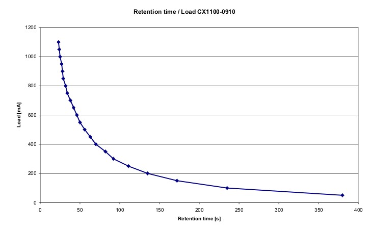
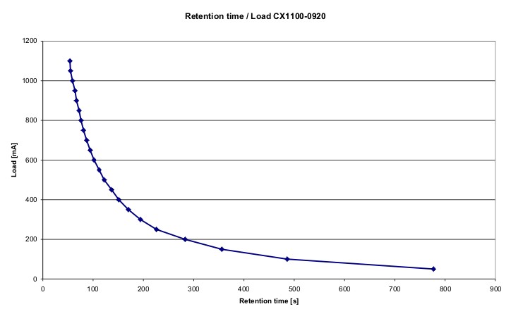
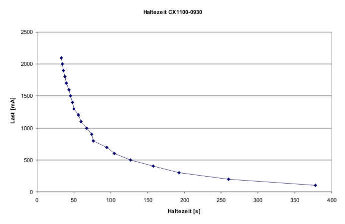
The other UPS module have a maximal load of 1100 mA. The results are shown below.
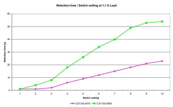
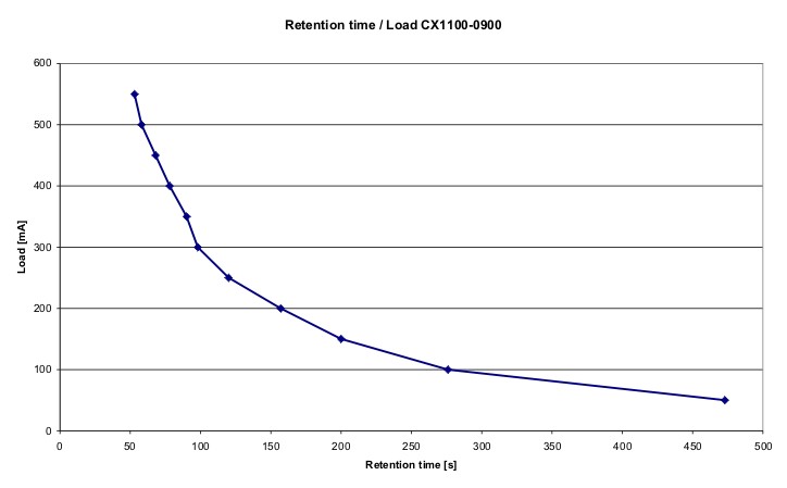
Retention time in relation to load at switch setting 0
For maximal discharging the torque switch is set to 0. The load is increased by steps of 50 mA. The curves show the measured retention times.
Measurements with sample configurations
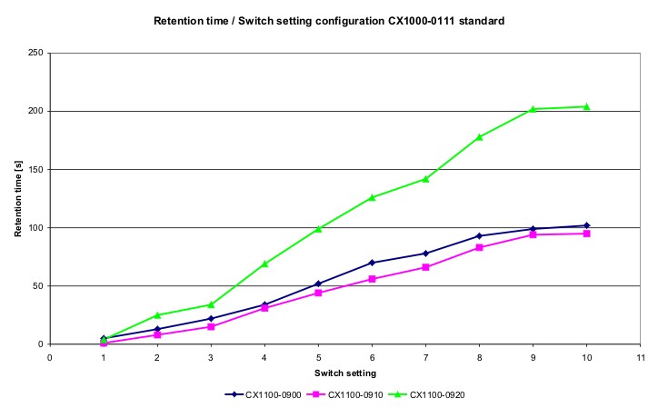
As an example for a real load some Embedded PC configurations have been tested. The retention time was measured in relation to switch setting. The first test configuration is a CX1000 System (CX1000-0111) with typical configuration. Only the system interface N001 is connected to the basic system. The K-bus is supplied via the UPS, too. As terminals one digital input and one output terminal are connected to the bus. The system configuration shown in the picture.
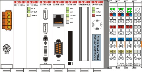
The retention times are:
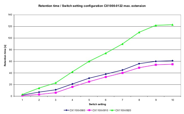
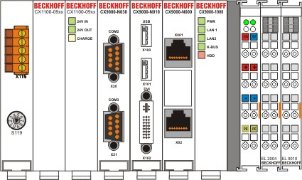
The second test configuration is an Embedded PC with maximal configuration. CX1000-System (CX1000-0122) with system interfaces N001 (2x USB, DIV), N002 (2x RS232), N003 (Audio), M200 (IP-Link-Master) und M319 (Profibus-Master). A keyboard with a hub and a mass storage device are connected to the USB ports as load. The system configuration is shown below.
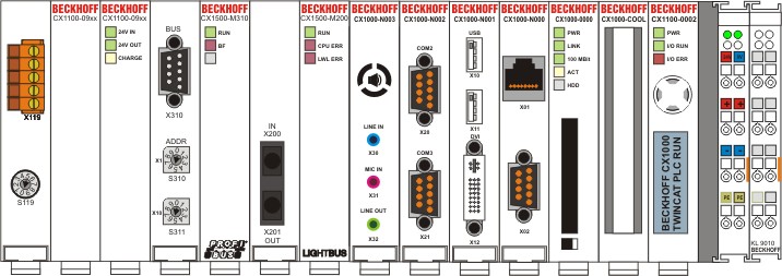
The light bus is shorted by a fiber optic cable. The PROFI bus master connection is connected to a BK3100 with terminals. The retention times are measured in relation to switch setting.
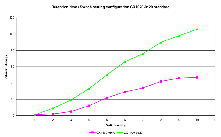
The third test configuration consists of a CX1020-System (CX1020-0120). The configuration is typical. Only the system interface N010 is connected to the basic module. The terminal bus is an E-bus. One digital output terminal is connected to the bus.
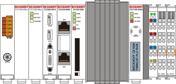
The results are as folows:
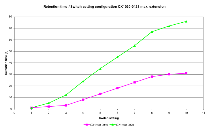
The next test configuration is a CX1020-system in maximal configuration. The test connections are the same as in the test 2.
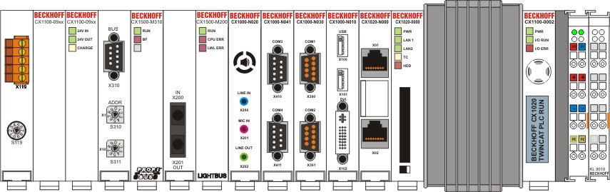
The retentions times are:
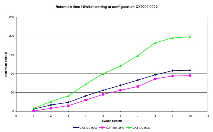
The last tested configuration is a CX900-system (CX9000-0002). The configuration is typical. Video, USB and serial interfaces are connected to the basic system. The load connected to the USB ports are the same as before.
The retention times are: