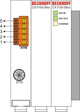
CX1100-09xx Connections
The UPS-Modules are supplied with power by 5-pin "Open Pluggable Connector". The other components of the embedded system are supplied via the PC 104 bus with 24V DC. (-15 % to +20 % tolerance)
|
Pin |
Assignment |
|---|---|
|
5 |
0 V DC OUT ( UPS output current) |
|
4 |
24 V DC OUT ( UPS output current) |
|
3 |
PWR FAIL (digital output) |
|
2 |
0 V DC IN (UPS incoming power supply) |
|
1 |
24 V DC IN (UPS incoming power supply) |
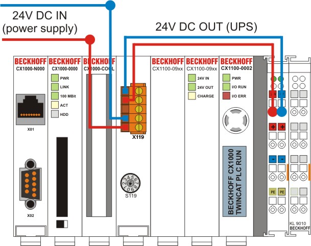
Connection to power supply
For power supply units with K-bus / E-bus connection (CX1100-0002, CX1100-0003 und CX1100-004) the supply is realized as follows:
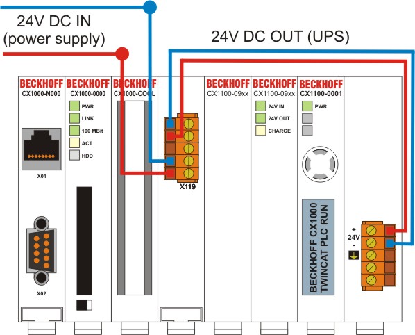
Though the power supply CX1100-0001 has no terminal bus interface the module is connected to the upper input connectors (24V). Older versions of the power supply are labeled with UPS -/+. These input are not used and more and must not be connected. The figure shows the correct connection.
Power-Fail-Signal Connection
The UPS modules can also be used to supply other bus couplers. To use the UPS module with the bus coupler the power supply has to be connected with the UPS. The power supply for the bus terminals has to be connected seperaty. This depends on the terminal bus load. The Power-Fail connection should be connected to a digital input terminal. (see picture below)
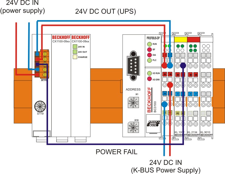
In case of power failure the UPS module rises the POWER-FAIL signal. The PLC program reads the input via the terminal bus and can shutdown the application. In this mode the control of the UPS module is controlled by the torque switch at the front side of the module.