Terminal Bus Analysis in PLC-Program
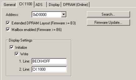
To analyze the terminal bus (K-Bus and IP-Link) the programmer can access the registers described in the architecture. The access to the PLC-program is realized via TwinCAT. To have the access to the necessary registers the extended DPRAM model has to be activated (only in Firmware > B3). The registers are described in the architecture of the terminal bus connectors.
Though the handling is identical for both sub busses the explaination is done generally.
For analysis four signals / variables are used:
- BusState (describes the state of the bus: 0 -> no error, 1 -> bus error)
- ErrorCode (same error code as the LED blink code)
- ErrorArg (same argument code LED blink code)
- Request[0] (output to request error codes / reset bus)
In the PLC program some external variables must be defined :
VAR

    k_bus_request AT %QX0.0     : BOOL;

    k_bus_err_code AT %IB0  : USINT;
    k_bus_err_arg AT %IB1   : USINT;
    k_bus_state AT %IB2     : USINT;


    ip_bus_request AT %QX0.1    : BOOL;

    ip_bus_err_code AT %IB3     : USINT;
    ip_bus_err_arg AT %IB4  : USINT;
    ip_bus_state AT %IB5    : USINT;

END_VAR
In the PLC program the analysis can be done as follows: (this is only pseudo code)
....

IF k_bus_state = 1       THEN       (* an error occured on K-Bus*)

   k_bus_request := TRUE;           (* request vaules for ErrCode and ErrArg *)

   CASE k_bus_err_code OF
     0 : return;            (* should not happen, though an error occured *)
     1 : CASE k_bus_arg OF
      0 : report error;     (* EEPROM checksum error *)
      1 : report error;     (* overflow in code buffer *)
      2 : report error;     (* unknown datatype *)
    END_CASE;
     2 : CASE k_bus_arg OF
      0 : report error;     (* programmed configuration, wrong table entry *)
      ELSE report error;    (* wrong table entry *)
    END_CASE;
     3 : report error       (* K-Bus command error *)
     4 : CASE k_bus_arg OF
      0 : report error;     (* break after power supply *)
      ELSE report error;    (* break after terminal 'k_bus_arg' *)
    END_CASE;
     5 : report error       (* K-Bus-error during register-communication with terminal 'k_bus_arg' *)
     9 : CASE k_bus_arg OF
      0 : report error;     (* checksum error in program flash *)
      ELSE report error;    (* terminal 'k_bus_arg' does not exist in boot configuration *)
    END_CASE;
    14 : report error       (* 'k_bus_arg'-th terminal has wrong format *)
    15 : report error       (* wrong number of bus terminals *)
    16 : report error       (* length of K-Bus data is invalid *)
   END_CASE

   k_bus_request := TRUE;           (* reset bus, if reason for error is removed, bus starts again *)

....
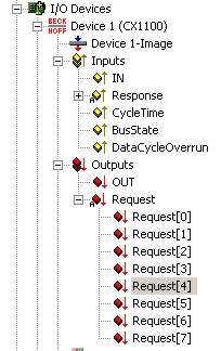
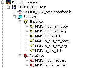
To make the control work, the register and the program must be linked in System Manager. If the PLC program is attached in System Manager the following signals are available:
Analog the registers of the terminal bus are shown in System Manager :
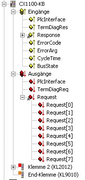
Link signals and variables :
k_bus_err_code with ErrorCode
k_bus_err_arg with ErrorArg
k_bus_state with BusState
and
k_bus_request with Request[0]
The same handling for IP-Link signals:
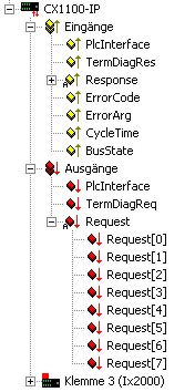
ip_bus_err_code with ErrorCode
ip_bus_err_arg with ErrorArg
ip_bus_state with BusState
ip_bus_request with Request[0]
If all signals are linked the programmer can load configuration and PLC program onto the system.
Firmware > B7
With a new firmware release B7 it is easier to access the diagnosis values. The solution described above clears the error code if the reason for the error is no longer present. With the firmware > B7 its possible to get the error codes directly in the case of the error. To access the error codes the Bit 4 in GCB must be set to 1. So for diagnosis its a good idea to set the bit in the initialization of error routine or PLC program. The bit must be linked to the bit 4 in GCB: