Mechanical assembly of the basic module
Assembly of the CPU and the power supply unit
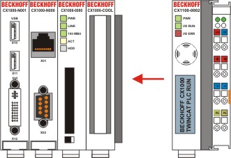
The individual modules are simply plugged together. The PC104 connector plugs should be handled carefully in order to avoid damage. When correctly assembled, no significant gap can be seen between the attached housings.
Engaging on the top-hat rail
On the bottom of the modules, there is a white tension strap, which is connected with a latching mechanism. These tension straps must be pulled down before attaching to the top-hat rail. This can be done using an ordinary screwdriver and a slight turn.
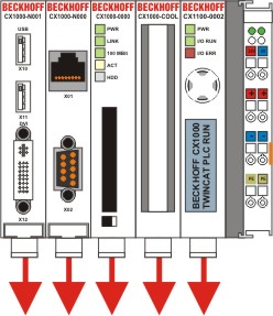
Then fix the CX1020 block on the top hat-rail using the latching straps. You should hear a soft click.
Notice | |
Do not force the module or apply excessive pressure! |
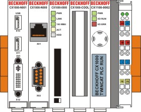
Only apply pressure at insensitive points of the housing (edges). Never apply pressure on the display, the buttons or movable parts of the CX10x0 system. After successful latching on the top-hat rail the straps should be pushed back to their original position.
At least the power connections must be installed. The upper connections "24v" and "0V" must be connected to power supply. If the power supply CX1100-0001 is used the power supply is connected via the 5-pin open style connector. (see connections / wiring)