Architecture of power supply CX1100-00x2
This power supply features, except for power supply, the following functions:
- Display 2 x 16 characters
- 4+1 navigation switch
- Non Volatile RAM
- K-bus connections
These functions are managed by the control program via the PC104 bus. The structure of the CX1100-00x2 is shown in the following figure:
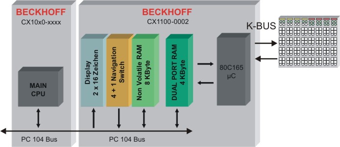
This power supply unit features the basic functions. These functions are described in the architecture overview. Further the k-bus is supported. The access to the bus is managed by a 4 KB dual-ported-RAM (DPRAM). A microcontroller (80C165) manages the data transfer to the k-bus. The DPRAM is accessed by the CPU (via PC104 bus) and the microcontroller.
The following figure shows the memory setup of the DPRAM:
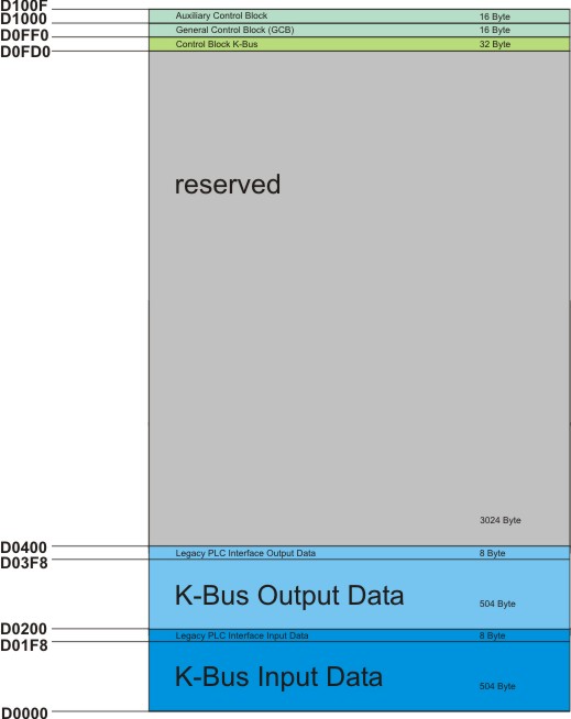
The memory image of the K-bus resides in the lower memory region (D000 to D0400). This region separates in input and output region. Since firmware version ≥ B3 it is possible to shift the I/O regions. In this way the process image can be adapted to the needed space. To each I/O-region the is a control block. Each block consists of 8 byte for diagnosis purpose. These regions can be shifted, too. The following table shows the structure of the interface. The offset addresses are default values.
|
Legacy PLC interface (inputs) | |
|
Offset |
Default |
|
0x1F8 [2] |
Diagnosis CX1100-0002 to K-Bus |
|
0x1FA [2] |
2 Byte PLC Interface from CX1100-0002 to K-Bus |
|
0x1FC [4] |
reserved |
|
Legacy PLC interface (outputs) | |
|
Offset |
Default |
|
0x3F8 [2] |
Diagnosis K-Bus to CX1100-0002 |
|
0x3FA [2] |
2 Byte PLC Interface from K-Bus to CX1100-0002 |
|
0x3FC [4] |
reserved |
The K-Bus Control Block (CB K-Bus)
This section describes the layout of the control block for the K-bus portion of a CX1100-0002 or CX1100-0003. This control block is located in the memory just below the General Control Block GCB.
|
CB K-Bus | ||
|---|---|---|
|
Offset |
|
Default |
|
0xFD0[2] |
K-Bus 2 byte plc interface to CX1100-0002/3 |
|
|
0xFD2[2] |
K-Bus 2 byte plc interface from CX1100-0002/3 |
|
|
0xFD4[2] |
K-Bus diagnosis to CX1100-0002/3 |
|
|
0xFD6[2] |
K-Bus diagnosis from CX1100-0002/3 |
|
|
0xFD8 |
K-Bus service request bitfield |
|
|
0xFD9 |
K-Bus service response bitfield |
|
|
0xFDA |
K-Bus error code |
|
|
0xFDB |
K-Bus error argument |
|
|
0xFDC[2] |
K-Bus base ptr Inputs |
0x000 |
|
0xFDE[2] |
K-Bus base ptr Outputs |
0x200 |
|
0xFE0-0xFE1 |
K-Bus cycle count |
|
|
0xFE2-0xFE3 |
K-Bus cycle time [µs] |
|
|
0xFE4 |
K-Bus bus status |
|
|
0xFE5-0xFEE |
Reserved |
|
|
0xFEF |
Retry counter |
|
K-Bus 2 byte plc interface to CX1100-0002/3 / K-Bus 2 byte plc interface from CX1100-0002/3
These two bytes for each direction - from the main CPU to CX1100 and back - special communication with the register model of the I/O microcontroller. Through this interface, a communication to K-Bus terminals can take place. The so called register model description can be found in the hardware description manuals of the terminals and bus couplers. This communication is typically used for extended diagnosis or configuration of terminals if they need to deviate from the delivery standard, e.g. changing the baud rate for RS232-terminals or gain/offset values with analog terminals.
K-Bus diagnosis to CX1100-0002/3 / K-Bus diagnosis from CX1100-0002/3
With these two bytes in each direction it is possible to retrieve diagnostic information from the attached terminals. Since the same diagnostic information is reflected in the process image input area per each terminals, there is in general no need to use this interface.
K-Bus service request bitfield / K-Bus service response bitfield
IThese two bytes contain a sequence of bits, by which certain service functions may be executed. The service function is invoked by setting the appropriate request bit, the controller executes and sets the response bit. Before the same function can be invoked again, the request bit must be set to zero and wait until the response bit is also set to zero. An execution error is signaled by raising response bit 7.
|
Bitfeld |
Bit 7 |
Bit 6 |
Bit 5 |
Bit 4 |
Bit 3 |
Bit 2 |
Bit 1 |
Bit 0 |
|
Request |
- |
- |
- |
- |
- |
- |
Free Run |
Reset Bus |
|
Response |
Error |
- |
- |
- |
- |
- |
Free Run Active |
Reset Done |
Reset Bus:
with this bit, a reset of the K-Bus may be performed. This is necessary after the occurrence of an error (detected by examination of the "Processdata error"-byte in the GCB) e.g. after a terminal has been pulled out. After performing the K-Bus reset, the error code and error argument may be read from the locations "K-Bus error code" and "K-Bus error argument" in the CB K-Bus. If there is no error after reset, the K-Bus is ready for operation again.
Free Run:
not implemented. Reserved for future use..
K-Bus error code K-Bus error argument
If the K-Bus operation fails (bad terminal, missing end-terminal, severe EMC interference), an error flag is raised in the GCB and after a K-Bus reset, these two bytes contain the error code and error argument of the occurred fault - if it still persists.
K-Bus base ptr Inputs / K-Bus base ptr Outputs
These two byte values contain the starting offset for the K-Bus input and output process image area. In most cases the default offsets should be left unchanged. When changing one of these offsets, a "Remap" or "Reset node" in the GCB service is needed. Also care must be taken not to overlap with the IP-Link process image area, because in the CB IP-Link the offset pointers for these areas may also be changed. The Beckhoff automation software TwinCAT makes use of this base ptr feature and compacts the I/O images in the best way possible.
K-Bus cycle count
This two-byte counter is incremented with each I/O-cycle.
K-Bus cycle time
This is the time elapsed between the initiation and termination of an I/O process image update (K-Bus + IP-Link ). The time is recorded in units of microseconds and starts with writing a new cycle request to the field "PD cycle request" and it stops with the termination response in the field "PD cycle ready", in case of CX1100-0002. In case of CX1100-0003, this time reflects only the K-Bus portion of the total I/O time.
K-Bus bus status
This byte value can take only two states:
- Byte = 0 → K-bus is ok
- Byte ≠ 0 → K-bus fault
This information is also reflected in the "Processdata error" field (bit0) of the GCB.
Retry counter
This is a retry counter which is incremented each time the microcontroller needs to redo a cycle because of a communication error. This counter can be used for judgment of the K-Bus signal quality.