Architecture of the power supply units
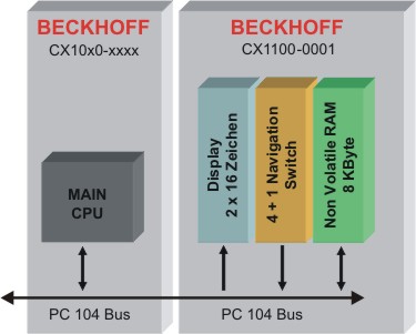
The four power supply units for the CX10x0-System accomplish more task than supporting the system with power. Each module has three basic functions. Additional each model supports different connection to communication busses. Caused by these different connections the internal architecture differ. At first the common functions are described.
All power supply feature, except for power supply, the following functions:
- Display 2 x 16 characters
- 4+1 navigation switch
- Non Volatile RAM
These functions are managed by the control program via the PC104 bus. The structure of the CX1100-0001 is shown in the following figure:
"General Control Block" (GCB)
The top 16 byte of the system control area (starting at the physical hex address D0000 + Offset FF0) form the general control block GCB, which holds the control byte required to start the I/O processing of the K-Bus and IP-Link.
The CPU of the main module controls the whole architecture. With memory mapped I/O regions data can be exchanged. The data needed to run the system is combined in the "General Control Block" (GCB). Its base address is "0xD1000". The figure shows the Data and the offset. Some registers are not needed in all units. So only the requested registers are mapped other addresses are masked out.
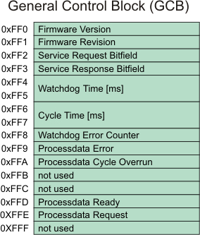
Firmware Version:
These two bytes contain the hex decimally coded version number of the CX1100 firmware. E.g. the first byte could show B3(hex): this results in firmware version B3.
Firmware Revision:
These two bytes contain the hex decimally coded revision number of the CX1100 firmware. E.g. the byte could show 00: this results in revision 00.
Service Request / Response Bitfield: (only for CX1100-0002 / -0003)
These two bytes contain a sequence of bits, by which certain service functions may be executed. The service function is invoked by setting the appropriate request bit, the controller executes and sets the response bit. Before the same function can be invoked again, the request bit must be set to zero and wait until the response bit is also set to zero. An execution error is signaled by raising response bit 7.
|
Bitfeld |
Bit 7 |
Bit 6 |
Bit 5 |
Bit 4 |
Bit 3 |
Bit 2 |
Bit 1 |
Bit 0 |
|
Request |
- |
- |
- |
- |
- |
Link Images |
Remap |
Reset Node |
|
Response |
Error |
- |
- |
- |
- |
Images Linked |
Remapped |
Reset Done |
Reset Node:
with this bit, a software reset of the 80C165 microcontroller can be performed. This is different from the hardware reset which may be performed in the Auxiliary Control Block (ACB).
Remap:
with this bit, the two-byte PLC interfaces normally residing in the input/output process areas can be remapped into the general control block for K-Bus and IP-Link. Thus the input/output process image areas can be kept clean and for the sole purpose of storing I/O-data.
Link Images:
if set, this bit links the K-Bus logically to the IP-Link in the case of error occurrence - meaning that if one of them stops operating, the other one is stopped as well. By default, this bit is set so stopping both I/O systems in case of error is the standard behavior.
Watchdog Time:
With the request of an I/O cycle through "PD cycle request", a watchdog timer with this specified millisecond time is started. If the cycle is not being restarted by a next "PD cycle request", the watchdog elapses and as a consequence the output process image is zeroed. This resets all outputs to a safe state (OFF). It also increments the value in "Watchdog Error Counter" by one. If another value than the default 100ms is written to this cell, a "Reset node" is needed to activate the change.
Cycle Time:
This is the time elapsed between the initiation and termination of an I/O process image update (K-Bus + IP-Link ). The time is recorded in units of microseconds and starts with writing a new cycle request to the field "PD cycle request" and it stops with the termination response in the field "PD cycle ready". For CX1100-0002 this time reflects the K-Bus update time, for CX1100-0003 it is the sum of K-Bus update time and IP-Link update time.
Watchdog Error Counter:
If the Watchdog Time exceeds the value in this register is increased by one. In this way the user can get the numbers of watchdog-time errors. (available since firmware revision B6)
Processdata Error:
This byte contains the information on the error status of the I/O blocks. The possible bit codes are:
|
Bitfeld |
Bit 7 |
Bit 6 |
Bit 5 |
Bit 4 |
Bit 3 |
Bit 2 |
Bit 1 |
Bit 0 |
|
Processdata Error |
- |
- |
- |
- |
- |
- |
IP-Link Error |
K-Bus Error |
The bit is set to "TRUE", if an error occurred. If both bits are zero, there is no error on either bus system. Error recovery may be attempted by invoking the "Reset bus" service in the corresponding CB of either K-Bus or IP-Link.
Processdata Cycle Overrun:
This byte contains a counter, which is incremented each time a new process data cycle is requested although the previous cycle has not yet completed. This can happen only due to a handshake programming error or if the user task cycle time is shorter than the time for I/O update.
PD Cycle Ready / PD Cycle Request:
These two bytes contain the request value and the ready value for operating a process data (PD) I/O cycle. The user program is supposed to write a pattern (e.g. an up-counter value ) to the request byte, thus triggering the I/O cycle. Once the I/O cycle is finished, the microcontroller will set the ready byte to match the request byte. A new request can then be written to the request byte.
"Auxiliary Control Block" (ACB)
The Auxiliary Control Block of CX1100 is a block of 16 bytes and starts at address D1000 (hex). It is a miscellaneous control block for controlling:
- the 2x16char FSTN LCD Display
- the navigation switch
- the hardware reset of the 80C165 microcontroller
The following schematic shows the layout of the ACB and is followed by a description of the single bits contained in it.
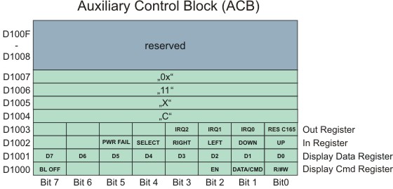
Display Cmd Register:
R/#W: This bit control the Read or Write operation for programming the display2x16 char LCD display.
DATA/#CMD: This bit controls whether the byte "Display Data Reg" holds a command or display data.
EN: This is the enable bit for executing the operation with the display controller.
BL OFF: If set, this bit turns of the backlight of the LCD Display. This feature may be used for blinking with the backlight, thus attracting the users attention to an important message on the display. It may also be
used to save power in the case of power loss and UPS operation.
Display Data Register:
These are the data bits for issuing commands or reading/writing data to the display controller. These bits are operated in conjunction with bits 0,1,2 of the Display Cmd Reg. For more detailed information please refer to the display controller documentation.
In Register:
These bits reflect the contact status of the 4+1 direction navigation switch on the front side of the CX1100 unit. These events may be used by a software for implementing a menu driven data input/output together with the LCD display.
Bit 0 UP
Bit 1 DOWN
Bit 2 LEFT
Bit 3 RIGHT
Bit 4 SELECT
Bit 5 PWR-FAIL (reserved for future use - do not use)
An example for access the switch is given in the detailed description of the switch.
Out Register:
Bit 0 RES C165
This bit resets the microcontroller 80C165 and restarts the initialization of the K-Bus and IP-Link circuit. For doing the reset, this bit must be set high and then set back to low. There is no need for an explicit hold time.
This bit may be used to recover from K-Bus faults such as removing a terminal during operation. It needs to be set at least once at startup or initialization of the user software before operating the k-Bus.
Bit 1 IRQ0 (reserved for future use - do not enable)
Bit 2 IRQ1 (reserved for future use - do not enable)
Bit 3 IRQ2 (reserved for future use - do not enable)
Memory region 0xD1004 to 0xD1008:
In this region the type of the power supply module is encoded. By adding the four registers the type description is given:
CX1101 CX1100-0001 power supply unit with display, 4 + 1 navigation switch and NOVRam
CX1102 CX1100-0002 power supply unit with display, 4 + 1 navigation switch, NOVRam and K-bus connection
CX1103 CX1100-0003 power supply unit with display, 4 + 1 navigation switch, NOVRam, K-bus-connection and IP-Link-connection
CX1104 CX1100-0004 power supply unit with display, 4 + 1 navigation switch, NOVRam and E-bus connection.
The Non Volatile RAM
The NOVRAM is one of the most important functions of the power supply unit. The access is realized via the PC104 bus. The mapping to PLC is realized by TwinCAT System Manager. Here needed variables can be defined and mapped to memory. Further details are given in the TwinCAT documentation.
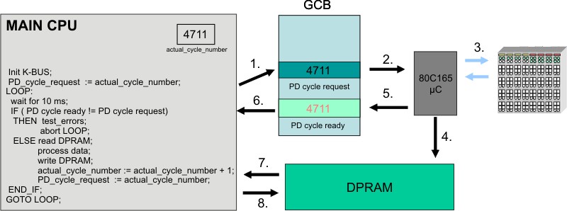
K-BUS and IP-LINK Operation
This section describes how to trigger the K-Bus (and in the case of CX1100-0003 also the I/O-boxes connected to IP-Link) in order to read input values and write output values. The procedure is the same for IP-Link, the description limits itself to K-Bus for textual simplicity.
The I/O operation is done through the bytes named "PD cycle ready" and "PD cycle request" in the GCB. The K-Bus cycle is triggered by a write operation to the byte "PD cycle request". Although the value being written to this byte does not matter (it is only the write operation which is important), it is recommendable write a counter-up value to this byte. The microcontroller for the K-Bus will react to the write operation by performing a K-Bus cycle and gathering the I/O data. Once the cycle is completed and the electrical signal input data are written to the DP-RAM, the microcontroller will set the content of byte "PD cycle ready" equal to the content of "PD cycle request", thus signaling the completion of the I/O cycle. The time required to run a K-Bus cycle depends on the number of terminals attached to CX1100: it is minimum 700 microseconds and typically well below 5 milliseconds. The K-Bus cycle time can be viewed by using the TwinCAT System Manager tool, by entering the exact terminal configuration.
At startup of the user program, before going into cyclic operation, it is mandatory to reset the K-Bus controller by triggering the "RES C165" bit in the Auxiliary Control Block section of CX1100. Please refer to the description of the ACB for how to do this.
The sequence of operating the K-Bus can be explained by assuming a cyclic automation task executed each 10 ms on the main CX1000 CPU:
Task cycle "n":
- check if K-Bus operation of previous cycle has finished: is "PD cycle ready" = "PD cycle request" ? Proceed if yes, issue error message and abort cyclic task operation if not, because a K-Bus cycle does not need 10 milliseconds to finish !
- read the input data from the DP-RAM (these are the input data gathered by the previous cycle "n-1" )
- write the output data to the DP-RAM (these are the outputs calculated by the previous cycle "n-1" ).
- increment and write the new value to "PD cycle request"
- perform task user code
Task cycle "n+1":
- check if K-Bus operation of previous cycle has finished: is "PD cycle ready" = "PD cycle request" ? Proceed if yes, issue error message and abort cyclic task operation if not, because a K-Bus cycle does not need 10 milliseconds to finish !
- read the input data from the DP-RAM (these are the input data gathered by the previous cycle "n" )
- write the output data to the DP-RAM (these are the outputs calculated by the previous cycle "n" ).
- increment and write the new value to "PD cycle request"
- perform task user code
Of course only the I/O bytes needed should be copied to or from the DP-RAM, since each read or write operation over PC104 is time consuming. Please note that the terminal outputs need a K-Bus refresh no later than 100 milliseconds, otherwise the watchdog in each terminal will shut off the outputs. This means that the task cycle time should be below 100 milliseconds. Also, if more than one cyclic automation task needs access to K-Bus I/O, it is important that only one task operates the K-Bus and the other tasks implement an I/O buffering in order to have a consistent I/O image. In this scenario, the task with the highest priority has the shortest cycle time and will trigger the K-Bus.
Please note also that it is assumed that in each cycle the integrity of the K-Bus is being checked by examining the "Processdata error" field in the GCB. Cyclic operation should be aborted in the case of an I/O error and user should be prompted for corrective actions. Cyclic operation can be resumed after resetting the faulty bus over the service request fields of the control block.