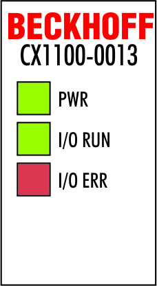
CX1100-0013 power supply LEDs
After switching on, the power supply immediately checks the connected Bus Terminal configuration. Error-free start-up is signaled by the red "I/O ERR” LED being extinguished. If the ”I/O ERR" LED blinks, an error in the area of the terminals is indicated. The error code can be determined from the frequency and number of blinks. This permits rapid rectification of the error. Though the power supply supports two bus systems both bus errors are reported by the "I/O-Err" LED. An error on K-Bus is reported by rapid blinking. One long flash (app. 2 sec.) reports errors on IP-Link-bus.
|
Display |
LED |
Meaning |
|---|---|---|
|
|
Power |
Power supply The LED lights up green when the power supply is correct, but red if there is a short circuit. |
|
I/O Run |
K-Bus diagnostics / IP-Link diagnostics The green LED lights up in order to indicate fault-free operation. "Fault-free" means that the communication with the fieldbus system is also running. | |
|
I/O Error |
K-Bus diagnostics / IP-Link diagnostics The red LED flashes to indicate an error. The red LED blinks with two different frequencies. |
|
Fast blinking |
Start of the error code |
|---|---|
|
First slow sequence |
Error code |
|
Second slow sequence |
Error code argument |
LEDs for K-Bus diagnosis
|
Error code |
Error code argument |
Description |
Remedy |
|---|---|---|---|
|
Persistent, continuous blinking |
|
EMC problems |
- Check power supply for overvoltage or undervoltage peaks |
|
1 pulse |
0 |
EEPROM checksum error |
Revert to the manufacturer’s setting |
|
1 |
Code buffer overflow |
Insert fewer Bus Terminals. The programmed configuration has too many entries in the table | |
|
2 |
Unknown data type |
Software update required for the power supply | |
|
2 pulses |
0 |
Programmed configuration has an incorrect table entry |
Check programmed configuration for correctness |
|
n (n > 0) |
Table comparison (Bus Terminal n) |
Incorrect table entry | |
|
3 pulses |
0 |
K-Bus command error |
- No Bus Terminal inserted |
|
4 pulses |
0 |
K-Bus data error, break behind the power supply |
Check whether the n+1 Bus Terminal is correctly connected; replace if necessary. |
|
n |
Break behind Bus Terminal n |
Check whether the Bus End Terminal 9010 is connected. | |
|
5 pulses |
n |
K-Bus error in register communication with Bus Terminal n |
Exchange the nth bus terminal |
|
9 pulses |
0 |
Checksum error in Flash program |
Revert to the manufacturer’s setting |
|
n (n>0) |
Bus Terminal n is not consistent with the configuration that existed when the boot project was created |
Revert to the manufacturer's setting which will clear the boot project. | |
|
14 pulses |
n |
nth Bus Terminal has the wrong format |
Start the power supply again, and if the error occurs again then exchange the Bus Terminal. |
|
15 pulses |
n |
Number of Bus Terminals is no longer correct |
Start the power supply up again. |
|
16 pulses |
n |
Length of the K-Bus data is no longer correct |
Start the power supply up again. |
Error code argument
The number of pulses indicates the position of the last Bus Terminal before the fault. Passive Bus Terminals, such as a power feed terminal, are not included in the count.
In the case of some errors, rectification does not cause the power supply to leave the blink sequence. The power supply can only be restarted by switching its supply voltage off and on again.
Note:
The supply voltage of the power supply unit, which is necessary to supply power to the CX1000 system, must not be interrupted in the middle of operation. Switching off the supply voltage to the power supply unit refers here to the power supply on the power contacts.
LEDs for IP-Link-Bus-Diagnosis
After a long flash (app.. 2 sec.) an IP-Link-Bus error has occurred. The following tables describe the error codes and help to find the reason for the error. IP-Link errors most often turn out to be a result of inappropriate use of the optical fiber.
|
I/O Err |
Description |
Remedy | ||
|---|---|---|---|---|
|
off |
No data exchange |
Module in synchronous mode or - activate Profibus cyclic data | ||
|
1 |
0 |
EEPROM checksum error |
Set manufacturer’s setting with the KS2000 software | |
|
2 |
Reserved |
- | ||
|
3 |
Break location has been recognized |
interruption before the master's receiver | ||
|
3 |
n |
Break location has been recognized |
n-th module before the master's receiver | |
|
3 |
n |
m |
Break location has been recognized |
(n*10)+m-th module before the master's receiver |
|
4 |
n |
Too many faulty telegrams have been detected (more than 25%) |
The optical fiber wiring in front of the nth extension module should be checked | |
|
5 |
n |
Register access to complex modules has failed |
Check the nth module | |
|
11 |
n |
Complex module working incorrectly |
Exchange the nth module | |
|
12 |
n |
More than 120 modules in the ring |
Connect fewer modules | |
|
13 |
n |
nth module unknown |
Firmware update required | |
|
off |
Module is exchanging data |
no error | ||
NOTICE | ||
If an error occurs on both terminal busses (K-Bus and IP-Link-Bus) the error on K-Bus is reported at first. The IP-Link-Bus error is reported as second. Both error codes are introduced by their typical blink signal. | ||