Mechanical installation of the fieldbus connection
Installation of a fieldbus connection involves several steps:
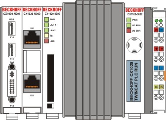
1. Removing the cover of the basic CX1020 module
In order to be able to connect the fieldbus to the basic CX1020 module, the cover of the basic CX1000/CX1020 module has to be removed first. This is achieved by applying slight pressure on the cover.
2. Assembly and connection to the CX1000/CX1020 configuration
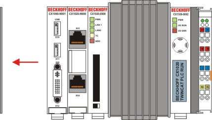
Since the CX1000 configuration is already positioned on the top-hat rail, the assembly first has to be pushed onto the top-hat rail. To this end the latching mechanism has to be released by pulling the white straps downwards.
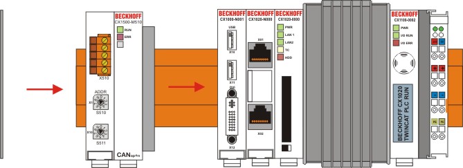
The assembly is connected to the existing CX1000/CX1020 configuration by simply plugging the two units together. Care must be taken that the plug of the PC104 interface is not damaged.
When correctly assembled, no significant gap can be seen between the attached housings. Finally, the white straps are returned to their original position, so that the locking mechanism engages.
3. Install cover
If the connection area does not have a closing cover on the left-hand side, the cover that was previously removed should be pressed over the connections until it audibly engages.
Note:
If the CX1000/CX1020 configuration is not positioned on the top-hat rail, it is possible to connect the assembly with the CX1000/CX1020 configuration first and then latch the whole module onto the top-hat rail. The installation is described in section Installation and wiring.
Note:
A locking mechanism prevents the individual housings from being pulled off again.