Setting up: Device EtherCAT with cable redundancy
If a downlink port of the CU2508 has been set up as an EtherCAT device, a further port can be used as a 2nd EtherCAT port for the purpose of cable redundancy.
The "TwinCAT cable redundancy" supplement serves to keep the EtherCAT system in operation in the case of an unforeseen interruption in communication due to cable breakage. The system is single-error tolerant. This achieved by the ring closure of the EtherCAT system to the controller. If more than 1 error occurs, slaves drop out of the communication. They are only readmitted after all connections have been restored.
 Fig.44: TwinCAT EtherCAT cable redundancy
Regarding this, refer to the principle explanations in the EtherCAT system documentation.
The combination of the EtherCAT cable redundancy and Distributed Clocks technologies is possible using the CU2508.
Notes on EtherCAT cable redundancy
- The downlink port combination X1/2, X3/4, X5/6 and X7/8 should preferably be used for EtherCAT cable redundancy. However, if ports from groups X1..4 and X5..8 are mixed, the total internal processing time increases from approx. 2 µs to approx. 3 µs. This may need to be taken into account in applications with very short EtherCAT cycle times.
- If EtherCAT cable redundancy is activated, the CU2508 ports used is automatically set as the Distributed Clock ReferenceClock. The synchronization of the devices can thus be maintained even in the case of media interruption.
- During EtherCAT startup with Distributed Clock devices, the cable-redundant ring must be closed, and continuous communication must be possible, otherwise no synchronization is possible.
- An external Distributed Clocks synchronization of such an EtherCAT system is not possible for the time being.
Setting up EtherCAT cable redundancy
The EtherCAT configuration must be created on a CU2508 downlink port as described in the chapter "Setup: Device EtherCAT". The resulting topology can be displayed in the Device EtherCAT using the Topology button; see fig. Display of a simple EtherCAT topology.
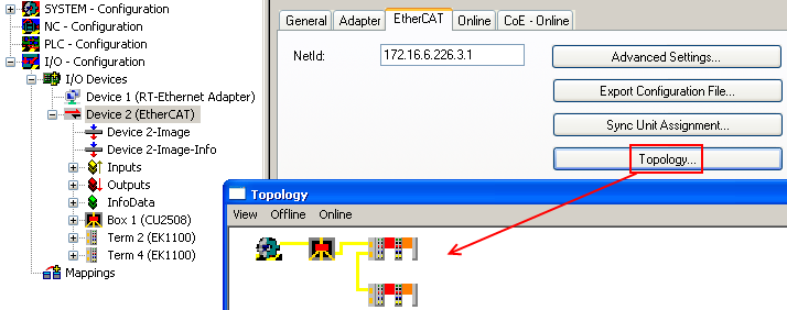 Fig.45: Display of a simple EtherCAT topology
The items below are to be specified in the following steps
- the control-side redundancy adapter, in this case on the CU2508
- the field-side redundancy adapter on the last EtherCAT slave
The EtherCAT redundancy port is specified in Device -> EtherCAT -> Advanced Settings.
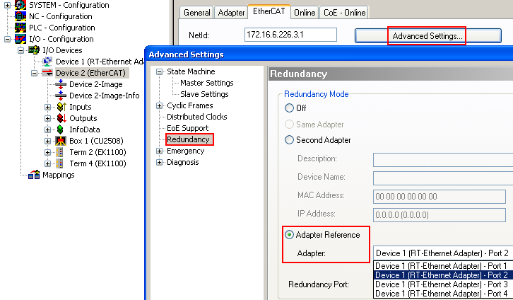 Fig.46: Specification of the redundancy port
|
Specification |
Meaning |
|---|---|
|
Off |
no EtherCAT cable redundancy |
|
Second Adapter |
physical adapter/Ethernet port of the controller |
|
Adapter Reference |
logical adapter such as in the CU2508 |
 | Number of ports A corresponding number of ports must be set to available in the settings for the CU2508 adapter. |
After specifying the redundancy adapter, it must be checked whether the System Manager has selected the correct EtherCAT slave port as the field-side connection point, see fig. Specification of the field-side redundancy port.
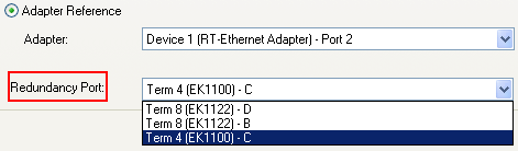 Fig.47: Specification of the field-side redundancy port
The correct selection can be checked in the Topology window.
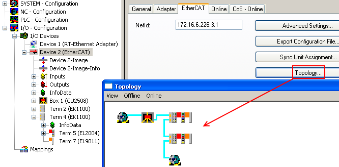 Fig.48: Checking topology with EtherCAT cable redundancy