TCP/IP via virtual switch
The virtual switch is a software component in TwinCAT that acts as an Ethernet Switch. The ports of this virtual switch are the ports of all EoE-capable devices that are present in the connected EtherCAT networks, e.g. EP6601-0002, EL6601 or EL6614.
From the operating system’s point of view, it appears as if the Ethernet devices are connected to a switch that is connected to the Gigabit Ethernet port.
Example

Activating the virtual switch
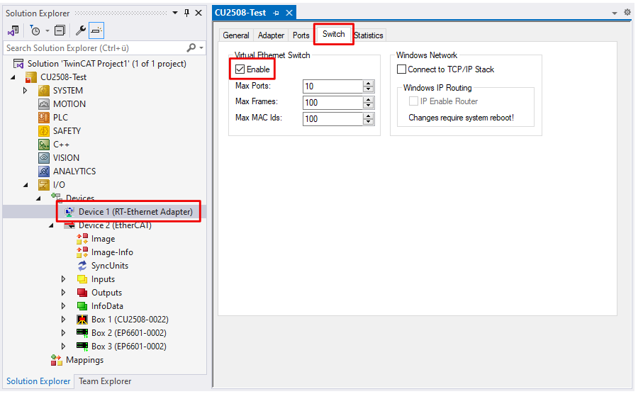
- 1. In the Solution Explorer, click on the “RT-Ethernet Adapter” device that was created in the chapter Integrating into a TwinCAT project.
- 2. Select the “Ports” tab and select the value “via EoE” from the drop-down menu “TCP/IP-Port”.
- 3. Select the “Switch” tab and check the “Enable” box in the “Virtual Ethernet Switch” field.
- The virtual switch is activated.
- 4. Configure the virtual switch using the other operating elements in this tab:
Name | Explanation |
|---|---|
Max. Ports | Number of ports of the virtual switch. Each EoE device (e.g. EL6601, AX5000) in the lower-level EtherCAT systems occupies one port. |
Max Frames | Max. number of buffered Ethernet frames. Can be increased if there are noticeable throughput bottlenecks. |
Max MAC Ids | MAC addresses of the connected devices stored in the internal Switch-Look-Up table. Must be larger than the maximum number of Ethernet devices ever connected to all systems. |
Connect to TCP/IP Stack | Connects the EoE switch to the internal Windows NDIS network layer |
IP Enable Router | This function is provided by the Windows operating system and is accessible via the registry or, in the case of embedded CX systems under Windows CE/WEC, via the CX-config tool. If activated, the NDIS network layer also mediates IP packets whose IP addresses do not correspond to the subnet mask. |
Notes
- The IP address of the used Gbit adapter and the subnet mask is used for communication. The EoE devices (printer, scanner, remote PC etc.) must therefore have their address within this area.
- The throughput depends among other things on the EtherCAT cycle time, the number EoE devices and the extent of utilization of the individual connections. The relevant notes in the documentation of the EoE devices must be observed.
- The EoE system can be connected to the NDIS layer via the switch “Connect to TCP/IP Stack” (fig. Data flow when using the CU2508 as an EoE switch, A).
- IP routing is an operating system function for routing IP messages between networks that are not on the same subnet. For example, between the devices 192.168.1.1 and 172.168.1.1, which are each in the mask 255.255.0.0.
This function is activated with “IP enable Router” (Fig. Data flow when using CU2508 as EoE switch, B). It is also available under Windows CE (CXconfig tool).