SFP diagnostics during operation (DDM)
SFP diagnostics is used to continuously monitor the operating parameters of the SFP transceiver used and the associated optical transmission link. The standardized data from the Digital Diagnostics Monitoring (DDM) can be retrieved in a Beckhoff EtherCAT device, provided that the SFP used supplies this data. In Beckhoff EtherCAT devices with SFP diagnostics, parameters specified in accordance with SFF 8472 can be evaluated:
- Temperature (Temperature, °C)
- Supply voltage (Voltage, V)
- Transmission power (Tx Power, dBm)
- Reception power (Rx Power, dBm)
- Bias current (Tx Bias, mA)
 | Note Not all SFP transceivers deliver all the values mentioned. Availability, scope and resolution of the DDM data are manufacturer-specific and can be found in the respective SFP data sheet. |
SFP Process image
The following PDOs can be selected in the process image of the SFP diagnostic data. It is also possible to work without DDM PDOs. By default, the DDM status is selected for all SFP ports.
PDO | Meaning |
|---|---|
0x1An0 | DDM Status Channel x |
0x1An1 | DDM Ext. status channel x |
0x1An2 | DDM Values Channel x |
0x1An0: DDM Status Channel n
The following basic information on the functionality of the SFP ports is displayed in the status.
Name | Type | Description |
|---|---|---|
SFP Present | BIT | An SFP is plugged into the port. |
Rx Signal Detected | BIT | The SFP receives an optical signal. |
Input Cycle Counter | BIT2 | The 2-bit counter is incremented as soon as new DDM data is available from the SFP. |
DDM Warning | BIT | At least one DDM size is in the warning area. |
DDM Alarm | BIT | At least one DDM size is in the alarm area. |
DDM Diagnostics Available | BIT | The plugged SFP supports DDM. |
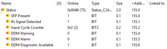 Fig.48: 0x1An0: DDM status
 | Note on the Working Counter If the EtherCAT connection behind the EtherCAT SFP device is disconnected, SFP diagnostic data in the process data may lose its validity even though the EtherCAT device is in OP. Therefore, wcState should be monitored and a separate SyncManager created for the SFP device. |
0x1An1: DDM Ext. status channel n
The extended status can be used to examine in more detail which DDM size is too high or too low. For each DDM size there are the bits Alarm High, Alarm Low, Warning High and Warning Low. The bits and associated limit values originate from the SFP transceiver and can be read out via the CoE interface in object 0xA0n0 (see Check CoE information on the SFP).
0x1An2: DDM Values Channel n
The live measured values of the SFP diagnostics can be viewed in this PDO.
Name | Type | Unit |
|---|---|---|
Temperature | REAL | °C |
Voltage | REAL | V |
Tx Bias | REAL | mA |
Tx Power | REAL | dBm |
Rx Power | REAL | dBm |
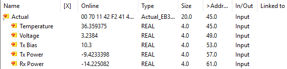 Fig.49: 0x1An2: DDM Values