Structure
Figure 1 shows the structure of the device as an example of all CP79xx versions.
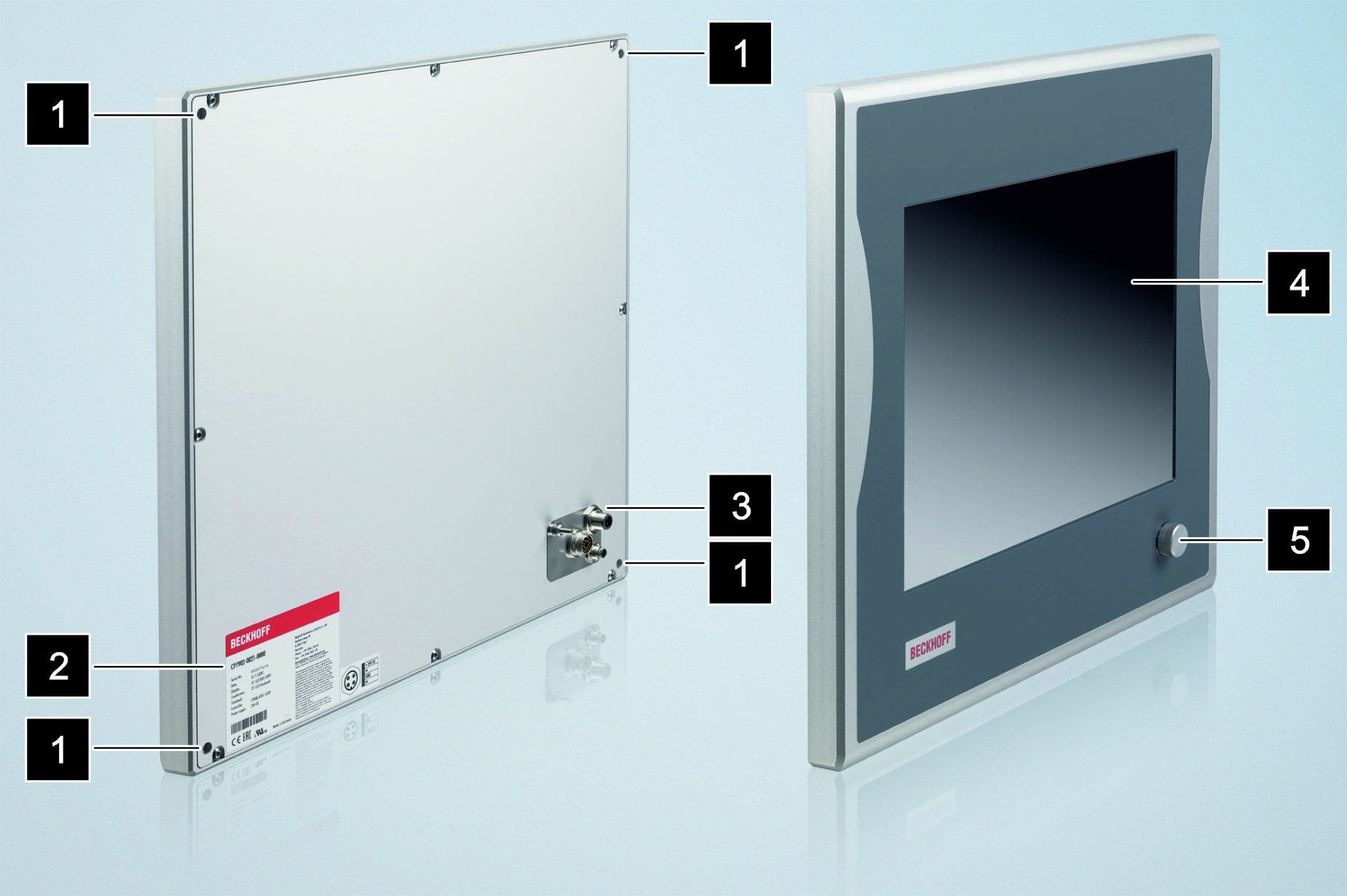
No. | Component | Description |
|---|---|---|
1 | 4 threaded holes M6 x 18 mm | For installation on the wall |
2 | Name plate | Information on the control panel equipment |
3 | Connection section | Access to interfaces |
4 | Display and touch screen glass | Operating the control panel |
5 | Optional USB socket | Connection of peripheral devices |