Control cabinet installation
Notice | |
Extreme environmental conditions Extreme environmental conditions can cause damage to the device.
|
Notice | |
Lack of air circulation Incorrect installation of the device prevents air circulation in the device and thus causes overheating and impaired functioning.
|
Notice | |
Incorrect installation Mounting the device in a way that deviates from the documentation can impair its functionality.
|
The device is designed for installation in a control cabinet for machine and system engineering. The environmental conditions specified for operation must be observed.
Dimensions
For the device dimensions, please refer to the “Technical Drawings” section in the Download Finder on the Beckhoff website. Enter the desired device in the search bar.
All dimensions are in mm.
Preparation of the control cabinet
The control cabinet must have the required installation cutout according to the device dimensions of the panel PC.
The wall thickness must be between 1 mm and 5 mm for installation. After installation, be sure to check the tightness between the panel PC and the wall.
Please also note the following for installation in a control cabinet:
- Ensure that there is 5 cm of free space above and below the device for air circulation.
- Position the panel PC such that reflections from light sources on the screen are avoided as far as possible.
- For the correct installation height, use the position of the screen for guidance. This should always be optimally visible to the user.
- Do not expose the panel PC to direct sunlight.
Installation in the control cabinet
Once you have made the required cutout in the control cabinet, you can install the device in the control cabinet. Clamping levers are provided at the rear side of the housing for mounting of the device. When delivered, the clamping levers are folded down onto the device.
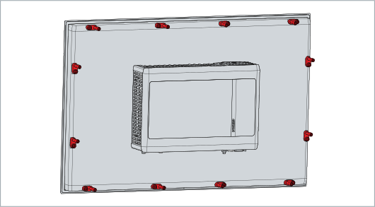 Fig.11: Delivery state clamping lever
To mount the device in the control cabinet, follow the steps below:
- 1. Insert the device in the intended position in the control cabinet wall. Make sure that the device is secured against falling out until it is fastened properly.
- 2. Turn the clamping levers 90° outwards (sections A and B).
- 3. Tighten the clamping levers with a 3.0 mm Allen key (section C).
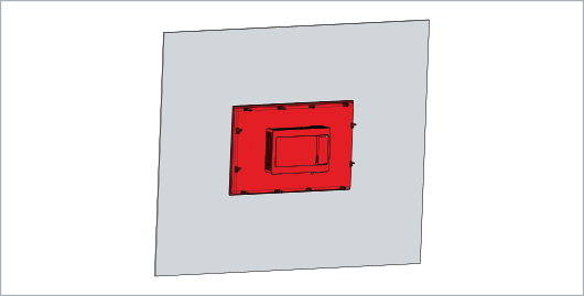 Fig.12: Wall positioning
- You have installed the device in the control cabinet.
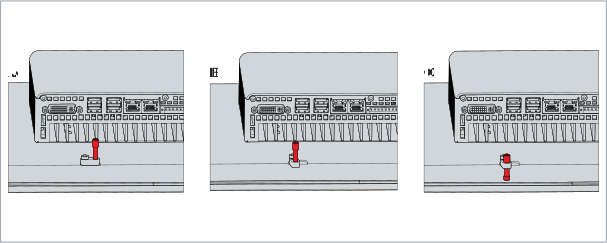 Fig.13: Control cabinet installation